@t3p3tony
Hi Tony,
Thanks for the prompt response and support. 
@t3p3tony said in Printing metal and ceramic with Duet 3:
There is no voltage boost options on Duet, the highest voltage available is the VIN voltage supplied.
This makes sense. Thanks for confirming.
@t3p3tony said in Printing metal and ceramic with Duet 3:
Have you looked at the documentation here:
https://docs.duet3d.com/en/Duet3D_hardware/Duet_3_family/Duet_3_Mainboard_6HC_Hardware_Overview#h-5v
I did indeed read this after asking the question. I initially missed the little click over tab and the distinction between revision 1.01a and 1.01...  I have the version 1.01a.
@t3p3tony said in Printing metal and ceramic with Duet 3:
You should have received a connector pack with the Duet which you can use to replace the connectors on the ender three wires with the JST VH connectors on the Duet using a standard crimping tool.
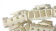
I cannot seem to figure out the orientation the supplied connectors are intended to fit onto the pins on the Duet however... 
In this attached image, is it the tight spaced holes on 0.1" pitch that is intended to connect to the big pins on the duet? the duet pins seem to be 0.2" space and the pins are too big for the holes in the connector... When I try the opposite side(the one with the bigger holes in) with the crimps inserted, the fit to the duet pins is very loose... Is this intentional?
@t3p3tony said in Printing metal and ceramic with Duet 3:
The heated bed output can switch a separate voltage supply, up to 36V, so you could provide 36V to your boost convertor via that. What I want to understand is why you need to switch the MOSFET power supply from the Duet. An alternative would be to use a appropriate voltage supply directly to your MOSFETs, with then the control of those coming from the Duet
To answer your question:
I want the duet to be able to control the behavior of each of the 8 individual the print head nozzles directly with nozzle specific g-code commands. I am essentially only using the bed heater power to provide DC power, that is then switched via PWM (through the array of MOSFETS) by the 5V IO on the duet, to control the heating and cooling of the nozzle heaters. The heaters themselves respond at speeds on the order of 1-10 milliseconds to input voltages. With an input of 31 volt @ 500 mA, the heaters can heat from 20 C to 1300 C in ~1-10 milliseconds typically.
So you would suggest using power directly from the DC power supply(from its other open terminals), and boosting that to the required 31-40 volts instead of trying to tap power from any of the rails on the duet?
@t3p3tony said in Printing metal and ceramic with Duet 3:
How are you crafting the gcode to provide the correct firing sequences to the 8 mosfets?
On this point, I do not yet know. I am pretty new to all of this.
I was thinking of a single gcode instruction that would "turn a nozzle on for X milliseconds, then turn nozzle off" a quick, precisely timed pulse, with a unique identifier for each nozzle and a frequency or time value which determines how long the heater fires for? Basically, just turning an IO out pin on the duet on for 1-10 milliseconds, which then triggers the gate on one of the associated MOSFETS, firing the nozzle on the print head, and then quickly shutting off, and firing the next nozzle in the sequence (the row of the sliced layer presumably) then the print head rasters to the next row, and fires the nozzles again etc. etc.
Something along those lines 
Thanks again for the help!

 I have the version 1.01a.
