@Electriceye I had success with this LIS3DSH module:
AliExpress Feiyang store: https://www.aliexpress.com/item/1005006579261261.html
@Electriceye I had success with this LIS3DSH module:
AliExpress Feiyang store: https://www.aliexpress.com/item/1005006579261261.html
@Electriceye How it's possible to get the effector to move in a plane when it's controlled by 3 independent arms amazes me every time.
I hear what you're saying regarding the accelerometer. I think the weight of the wire running to the accelerometer is negligible compared to the weight of the print head, but I agree that less is better.
I did not have high expectations for the long ribbon cable (which had to be that long because the printer is, well, big). I wired to the temperature daughter board. It's an easy IDC connection at the Duet end, and I break out the Dupont connectors at the accelerometer end. There is a GND on pin 2 that separates the CS from the other signals. I think that might help. I didn't experience any issues or problems (for once!). The data looks reasonable, though it's transferred digitally so I'm sure problems would show up quite readily, though how it manifests I'm not sure.
I lied above. There were two issues. First one, I carefully checked all wires to make sure, absolutely, that I had the right signals from the accelerometer going to the right pin on the 10-way IDC. Then I went and plugged the 10-way connector into the wrong header. $#%!@#^& Fortunately the pin out on the other 10-way header meant I didn't kill anything.
The other thing that happened was that at one point I homed, then went to Z=0 on the big delta, and while the (5' cable from Digikey) was long enough for the initial testing, if the cable wraps itself around the effector, as wires like to do, it wasn't quite long enough and my 3D printed mount for the accelerometer went to 3D print heaven. $%#%&# again.
@moocowsia Neat to see all you have done.
I was wondering how to get a bit more speed from the Little Monster. Those blue aluminium carriages felt quite heavy, and by the looks of it quite a lot of material could be removed with no effect whatsoever. Have you thought about that as a mod?
What were the changes that you made that had the biggest effect?
The best thing I did was to move from an original (not knock off) E3D titan to a Bondtech LGX. Plus the change to textured PEI print sheet. I love textured PEI. I would like to try a direct mount Orbiter as they seem quite light, and I'm not a fan of the (even short) Bowden tube.
@dc42 said in hierarchy of control over gcodes, machine vs filament vs slicer:
The printer speed and acceleration limits should always be set no higher than the printer can reliably achieve. Otherwise you may end up with the slicer commanding the printer to move faster than it can manage, especially if you use the speed factor control in DWC or PanelDue to increase speed. You can of course set lower speeds and accelerations in the slicer settings.
That's something I have wondered in the past. If the slicer says to move at 100mm/s, and RRF has the speed limit set to 150mm/s, I would expect the printer to move at 100mm/s. If the speed factor control is then set to 200% in DWC, what happens? How fast does RRF drive the printer? 150 or 200mm/s?
I mention speeds, but presumably this applies to accelerations just the same?
I did look in the DWC manual for the speed factor control but it wasn't clear to me what limits were still imposed, if any.
This also had me wondering the other day as I was adjusting pressure advance as well as input shaping. In particular if pressure advance could result in extruder feed rates outside the limits that I had specified in RRF, and if some sort of clipping might occur if hard limits were enforced resulting in some obscure printing artefact. Same with input shaping and how the actual moves sent to move the head might look after going through a 'shaper filter' and whether they too were being 'clipped'. ... I have a background in audio design where clipping is just about the worst thing imaginable for a poor audiophile.
Now that I'm running two linear delta machines, where the amount the effector moves is not nicely related to the rotation of a single stepper but some combination of all three depending where on the print bed you are, it really starts to do my head in. Plus that's without considering bed mesh correction, tapering, skew adjustment, or others I don't even know about.
A user submitted a pull request to PrusaSlicer some time ago to fetch the printer speed and acceleration limits from the RRF object model and to modify the print time calculation to better reflect RRF when RRF is the selected firmware type; but unfortunately it wasn't actioned. See https://github.com/prusa3d/PrusaSlicer/pull/8087.
Oh, that's a shame, I for one would have found it useful.
@magnets99 just regarding the bridging, I have a couple of machines with the volcano hot end and they bridge fine. They are both running 0.6mm (used to run 0.8mm) nozzles. I have found them to be 'blobbly' and 'stringy' however compared with a 0.6mm V6 nozzle for example.
I hear you regarding all the configs all over the place. I'm not sure what to suggest, but I have spent ages trying to optimise a setting only to find out that it's being overwritten and my changes are having no effect whatsoever. Plus, I think slicers are not without bugs; I'm using the latest PrusaSlicer and I think there is at least one bug in there to do with what you see on the screen not being what is sent to the printer. I'm talking actual speed/volumetric flow. I also tried OrcaSlicer, and at least once managed to somehow produce a retraction tower test where the retraction didn't vary at all!
Here's a thought though. The latest PrusaSlicer (and similar) let you display actual print speed, but there's no way for this to be accurate unless PrusaSlicer is the component that's controlling the speed. So my current thinking is to set speed and acceleration high on the printer, and lower in the slicer. This means however that one can't make use of (say) hardware retraction on the printer because then that cannot be accurately displayed in the slicer, leading to great confusion. At least that's my experience.
I'm starting to find that tuning a printer is not that easy.
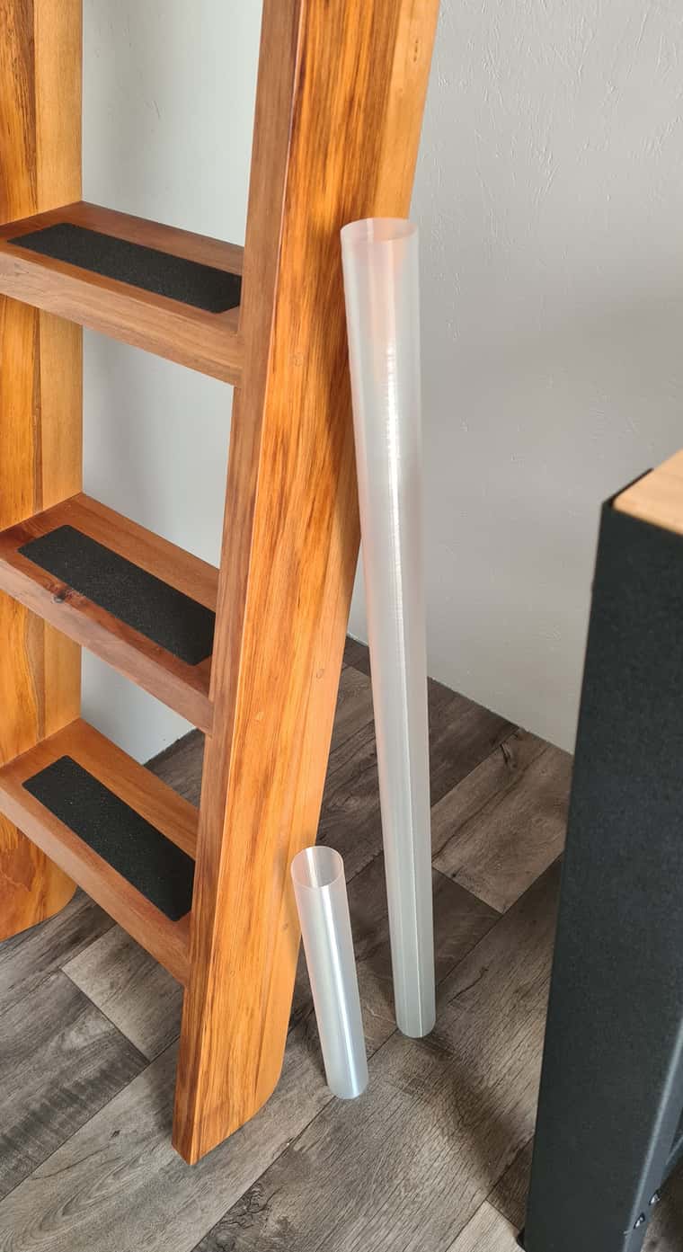
@moocowsia I'm still tuning it in, but I just recently printed a 50mm tube that's 950mm long. The delta printer is curious - the actual max height is just on 1000mm but the print volume is like a cylinder with a cone on top. If you want a flat topped anything it can't be the full height.
Here is the cylinder, on the right
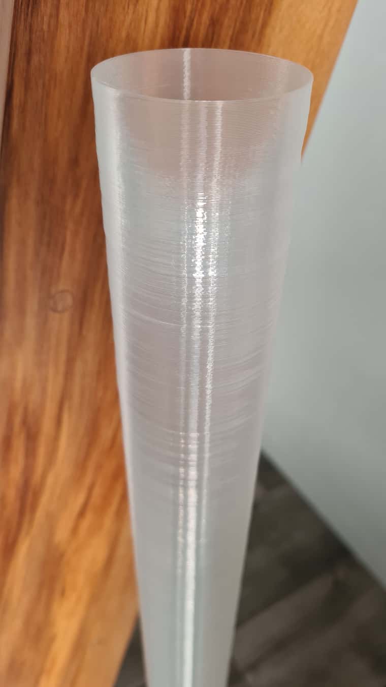
Unfortunately I couldn't be there while it was printing and I think it wobbled a bit as the print got taller, so from about 300mm upwards it's got minor irregularities. This is printed on a PEI sheet with magnetic sheet stuck to the original little monster glass print plate.
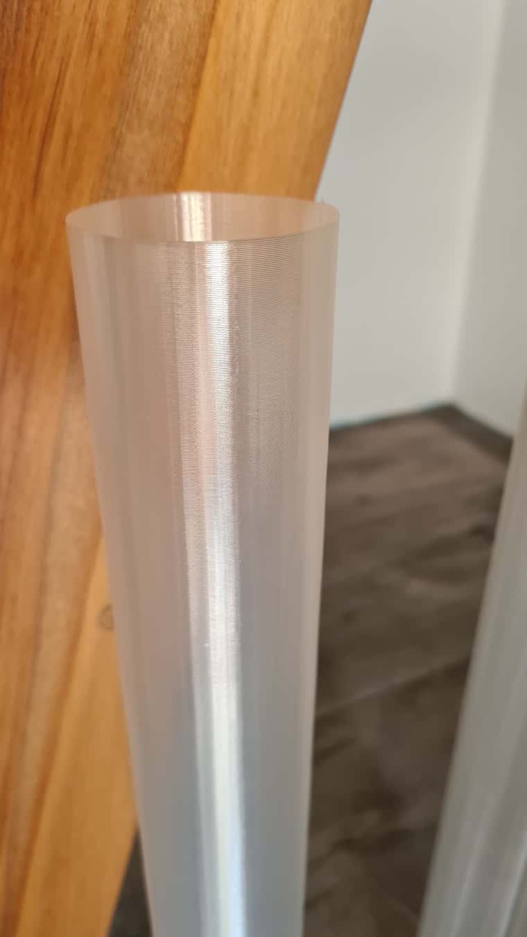
The shorter print is from the shorter delta. It's only 400mm tall, but could have been a bit taller. This doesn't have any wobble, being shorter, and I think also because it was printed on a glass print surface with little flex. Curiously, the print quality of the shorter tube is better, but I forget the print settings - it may just have been printed more slowly.
The circular shape on this one looks more like many straight lines rather than a smooth circle. Not sure why; there are many differences from software (different versions of PrusaSlicer) through to lots of hardware differences (stepper motors).
I'm still thinking of neat things to print. Any ideas? LOL.
@magnets99 In my experience, trying to correct for errors in "the foundation" by fiddling with the layers on top never really results in a great outcome. It may be ... passable, but I suppose it depends what you're aiming for in terms of result. I have had better success in accepting that, in this case, the heating bed is warped, and source/build a new one. That bed looks kind of thin anyway? Depending on where you are, you might be able to get a replacement for not too much. I was looking at the RatRig website a while back and their beds aren't so expensive, though you will need to buy a new heating pad too, alas.
I have those Energetic PEI print sheets on a number of printers and am very happy with them BTW. Also, I was not at all looking forward to the very much one time only job of sticking the magnetic sheet to a print bed, but it actually wasn't as difficult as I thought it would be.
@T3P3Tony No I did not. LOL. That's the problem by the looks of it. Just checking now I see that the tick turns slightly darker and most importantly, becomes clickable once the frequency field has been changed. I missed that.
Thank you!
Hi everyone,
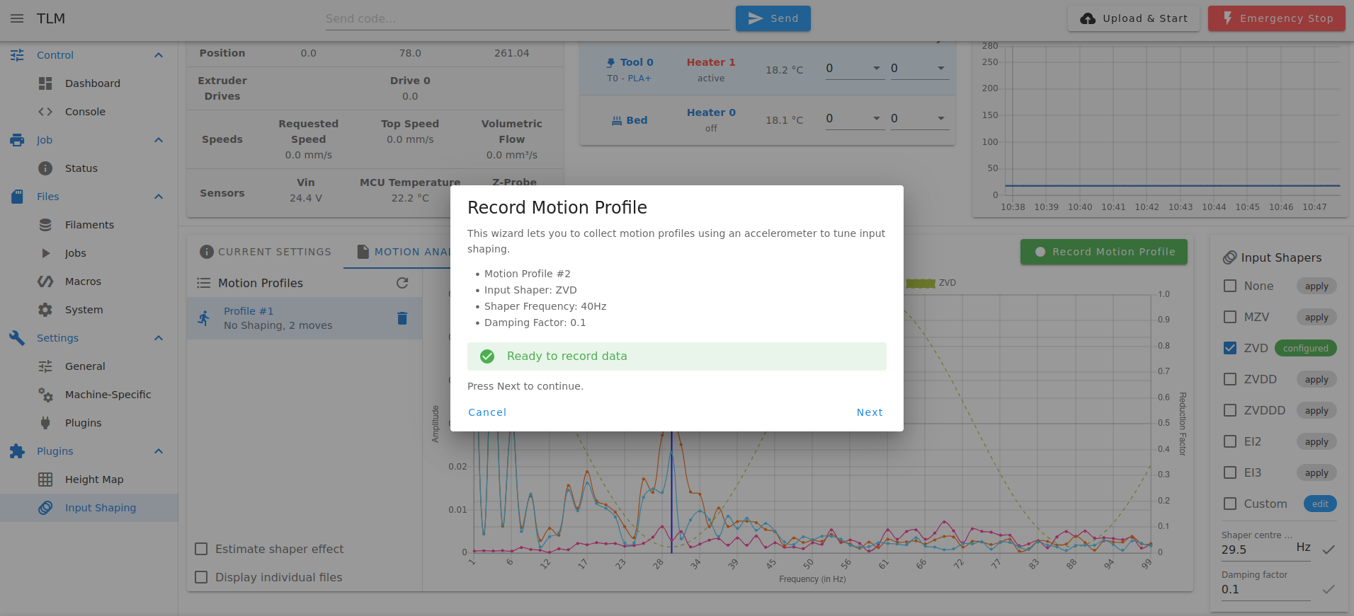
So over the break I have a bit of time to finally wire up an accelerometer and try out input shaping on my Duet 3 Mini 5+ powered Little Monster delta printer.
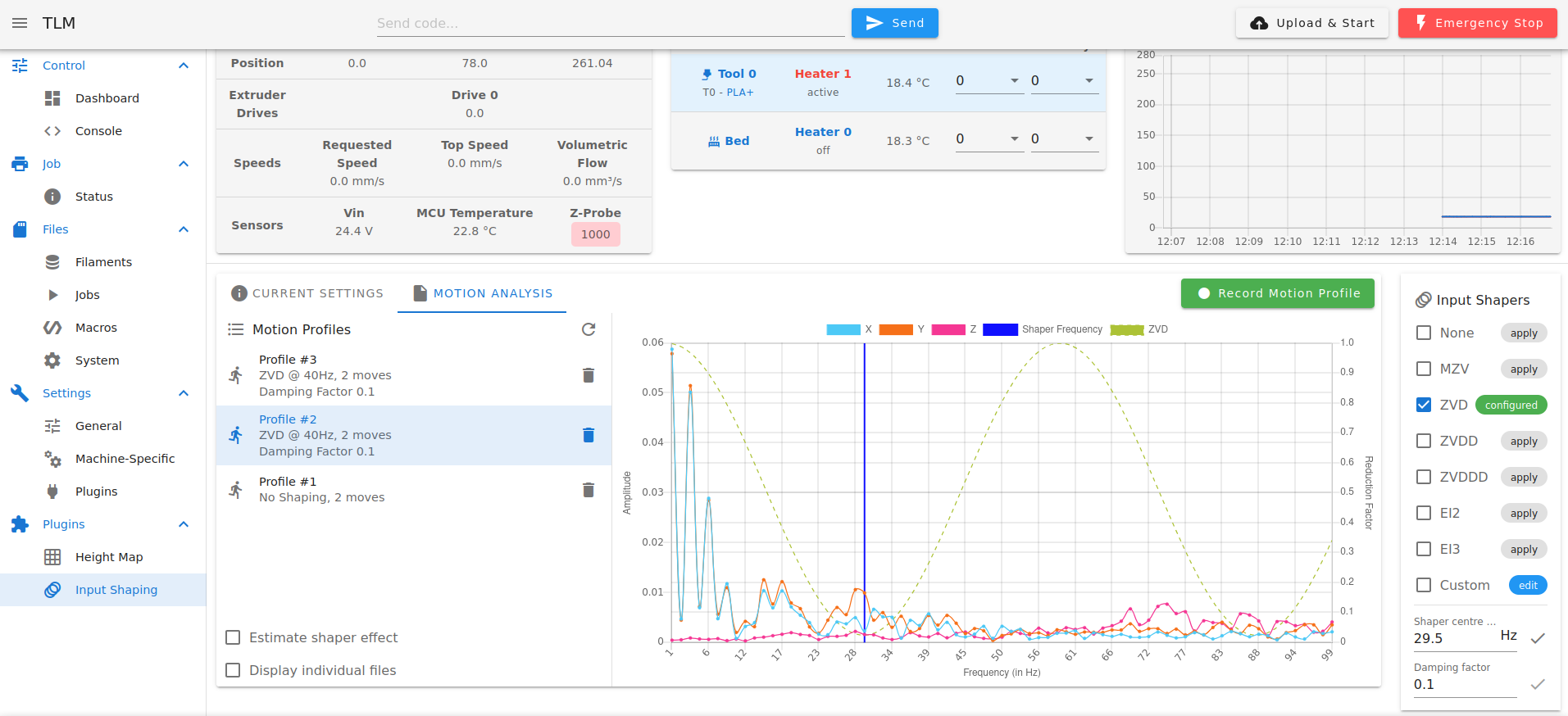
Almost everything looks right, except when I record a motion profile, the window that pops up shows a different frequency that what I've selected in the lower right of the screen.
Then, once the motion profile is created, its label shows 40Hz also.
What's going on? Where does the 40Hz comes from??? That's not the filter frequency I want.
I'm running the latest firmware, 3.5.4. I had a search of the forums to find out more and it looks like the input shaping will be changing for 3.6, so not sure if this is a bug and if so may not be worth chasing.
I was also wondering about the pros and cons of a lower damping factor. I couldn't find any information on this anywhere. DWC looks to use 0.1 as a default, but a lower value like 0.01 seems to lower resonances even further. No doubt there is some trade off by using a very low value though?
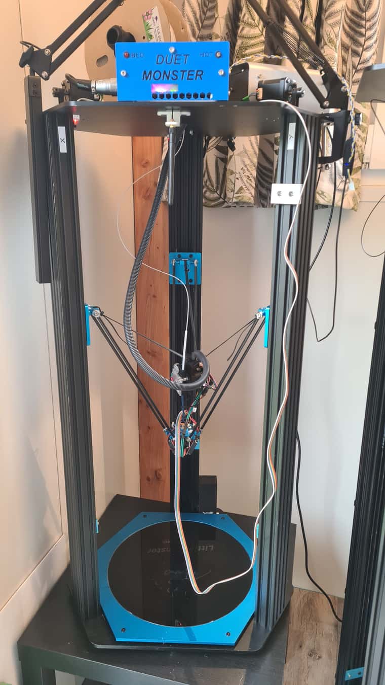
Here's the printer with accelerometer and cable in place, just for interest:
@T3P3Tony The heater is a combined 24V fan and 400W mains voltage heating element mounted towards the top on the left hand side of the enclosure. It brings in air from outside the enclosure, and, while it's not easily visible, the rear of the enclosure hangs over the back of the work bench, so the cooler air lower in the enclosure air exits at that point. I debated for a long time whether to just recycle (reheat) the air in the enclosure, but I hadn't worked with this kind of heater before and didn't know how hot the 'input' air could safely be, so I went for the safe option, and heat room temperature air. It looks like the heater is designed to be mounted on the outside of an enclosure, but I couldn't find any more guidance on the data sheet. This work space is not occupied, so I have no problems with potentially harmful ASA and other particles from engineering filament being blown into the room.
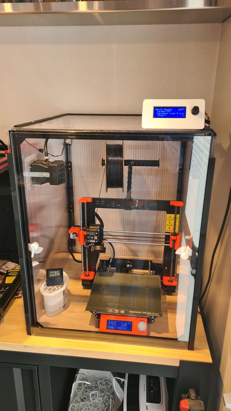
There is a blower fan that is used for the initial stage of heating in order to mix the air thoroughly throughout the enclosure.
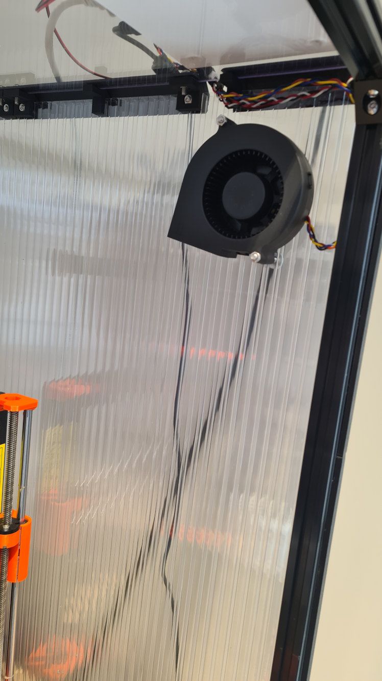
I have a single DS18B20 temperature sensor.
I'm using a simple heating thermostat algorithm (bang bang) to turn the heating element on and off. I found the location of the temperature sensor is critical and sensitive. At one extreme, if the sensor is in the hot air stream the heater will of course turn off far too early. At the other extreme, say if the sensor is tucked away in the enclosure frame tubing, the air in the enclosure gets far too hot before the heater will turn off. What I have found is that it's best where it is in the photo. I think it's best to have a sensor that reacts a little on the fast side, and just let the whole setup stabilise for a while, than risk wild temperature swings of a too slow sensor response. Yes, I could implement a PID system, but that would be more work.
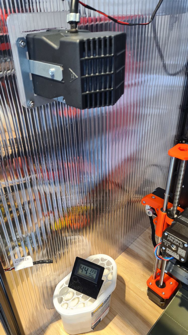
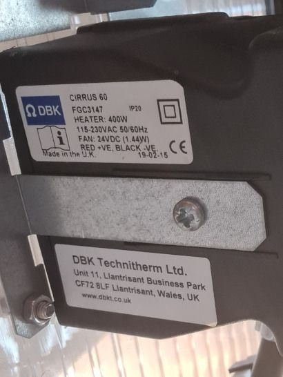
The heater unit spec is as follows.
As I say, this is not hooked up to a Duet, but the controller does have a serial interface that I designed to work with my Duet equipped machines. I'm hoping that one day I'll have an enclosure ready for those, and can do something similar.
Incidentally the enclosure is made from 8mm twin wall polycarbonate (roofing material), which is cheap, and for the parts where I want to see in it's made from 4mm Lexan (polycarbonate). This was about the best bang for the buck I could manage here in New Zealand, but it still cost a few hundred NZ dollars (maybe USD$200). The panels are joined together using brackets printed from eSun ABS-MAX which is UL94V0 rated filament. There is also a smoke detector nearby and a second one that is wired to an occupied area.
Regards,
-Martin
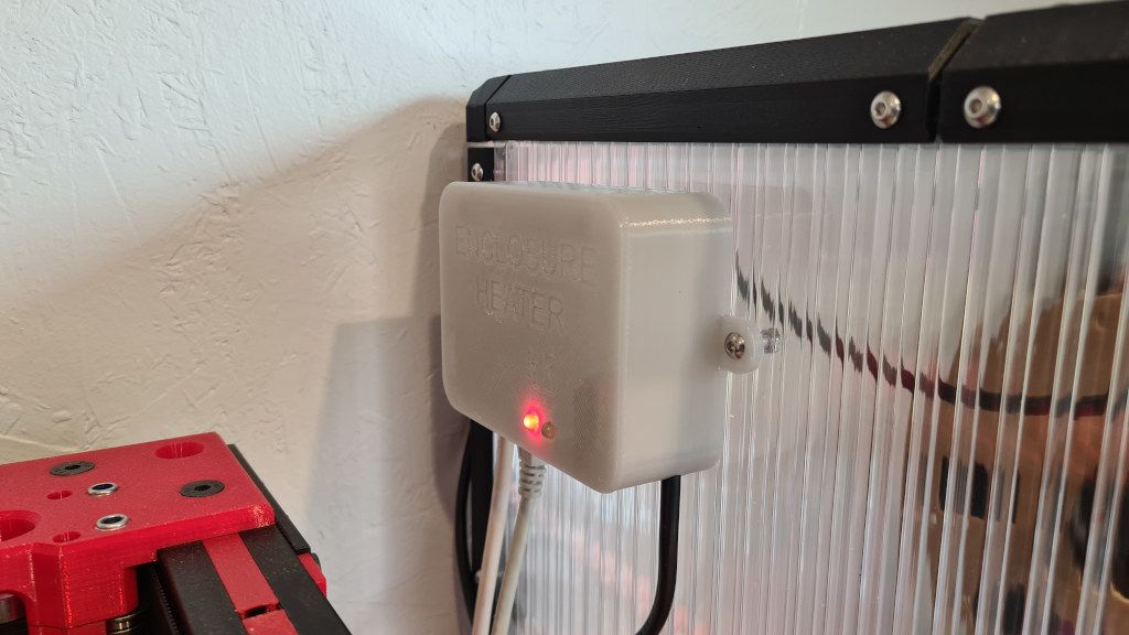
I thought I'd post an update on the enclosure heater design. While I still don't have an enclosure for the Duet3D delta printers I've built, I have an enclosure on a Prusa i3 that I do heat, using the same heater controller design.
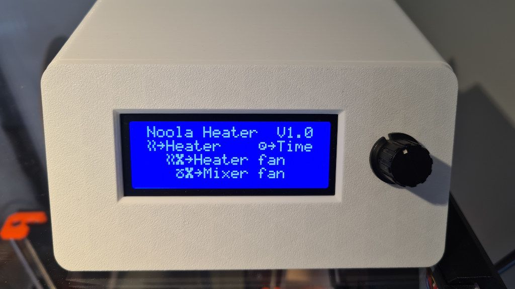
Splash screen:
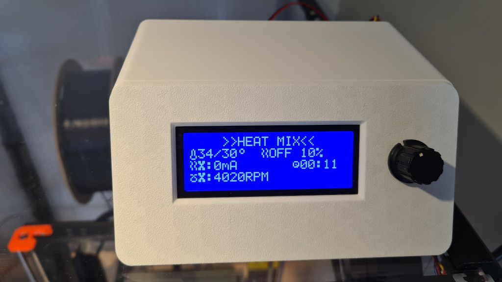
The unit measures temperature, current flow through the heater element fan and RPM of the 'mixer' fan. I have only briefly hooked up the serial port and it wasn't working, so something to investigate there. So it's all manual for now.
Driving the mains powered heater element is handled by a separate box using a relay.
@droftarts the parts arrived in due course and here is the made up adapter cable. I'm happy with it.
Note to all, this cable carries mains voltage and should be tucked out of the way and safely covered where you cannot touch it. This photo is with the cover removed for photo purposes.
This is not specific to a Duet powered printer, but I thought I'd write about it here anyway.
TL;DR Stop your delta printer effector crashing into the bed at power off using this small part.
For a while I've been tinkering with a Tevo Little Monster that I "repowered" with a Duet Mini 5+ board. The printer uses a BL Touch for sensing bed height. What I have found is that when the printer was powered off, the effector and arms would sometimes start to slide down and hit the print surface with a thunk. This wasn't the end of the world, but when powering the printer back on the BL Touch performs a self test, and with the effector firmly on the print surface this self test fails. The upshot is having to turn the printer off again, raise the effector off the bed by hand, and, while holding it off the bed, reach up and power on the printer.
More recently I modded another Little Monster with another Duet Mini 5+ board, and gave it 1.5m rails instead of the 1m rails on the original. This printer has the same problem when the power is turned off, except now it's even harder to reach the power switch on the top of the machine without raising the effector a long way up. A hassle more than anything. Anyway I wondered about how I could fix this issue and here is my solution.
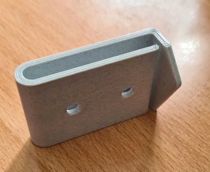
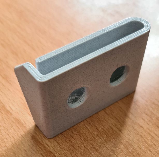
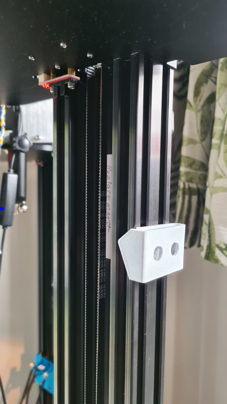
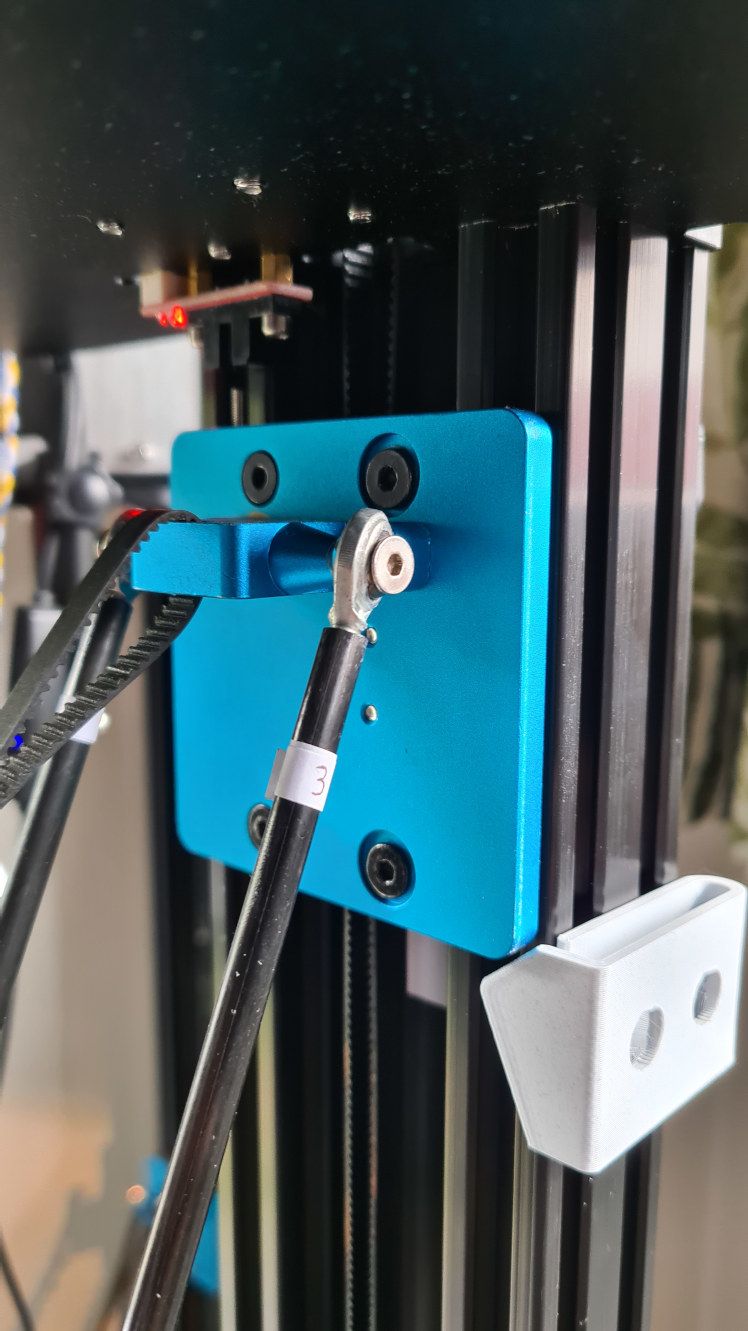
It's a flexible bracket that has enough resistance to stop the arms falling at power off, but not so much resistance as to stop the arms moving while under power. I position it a couple of mm below the rear carriage while the effector is in the parked position.
As these printers use 80x40mm C-beams the bracket I designed works with those only, however I think the idea could be applied to any other design. It's possible others have come up with something similar, but I didn't find anything in my searching. As is often the case the biggest problem may be figuring out what it's called!
Anyway, here are some photos. I use two screws with T-nuts to hold it on the rail.
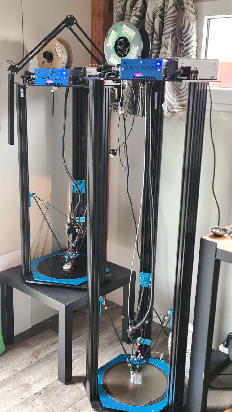
Here is a photo of the two monsters, showing the bracket in place.
As alternatives, and for which I'll use to make an adapter cable, I found these:
https://www.aliexpress.com/item/1005004265820177.html
They are described as 63080 with 6.3mm pitch. This seems, maybe to be something like a Molex Minifit. Maybe. Who knows with Ali Express. I'll have a close look at it when it arrives. I suspect it will be OK for voltage (230V here) and current (surely at most 2A for the TLM heater).
I would have ordered something nice from Digikey, but in the past I have spent a lot of time and almost lost my sanity trying to find housings, both male and female, and terminals to suit the wire gauge, all which fit together properly and for which I have a crimp tool. The Ali Express store RiccoDi seem to have lots of "sets" including male, female, and terminals which really helps with the headache.
This is the last piece of the puzzle for the printer conversion to 1.5m rails. I really hope it works and produces some at least half way decent prints.
Ahh rats, I think I found it on Digikey. 6.2mm pitch apparently. Unfortunately it seems to be obsolete.
Molex part 351-43-0201
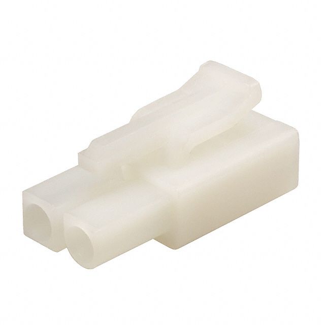
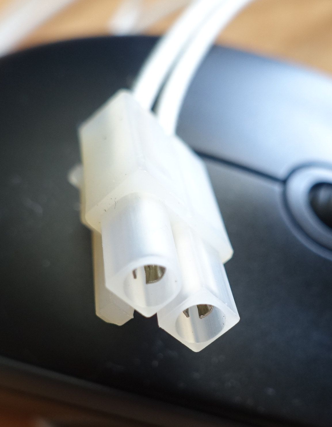
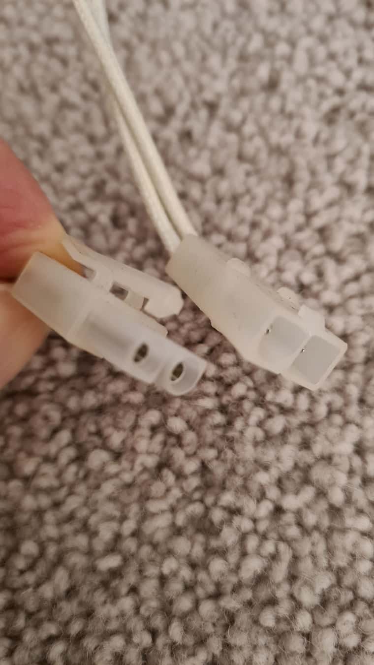
I measured the pitch again today and get 6.1mm, so maybe it's actually a 6mm pitch. A bit unusual. Notice also the half rounded housing keying. After much searching I've found that the rounded keying is unusual; most keyed connectors seem to use 45 degree angles.
Here's another photo; having real trouble taking a nice shot alas. I'll have a look on Digikey for 6mm pitch housings...
Another thing I could do is instead of making a complete new cable, or splicing the old one with some nasty solder joint would be to use the cable I have to make a short adapter to a new (and importantly, obtainable) connector. Kind of like...
heat bed--->X X<---->known male/known female<------- ... 2m to power supply end.
Hi everyone,
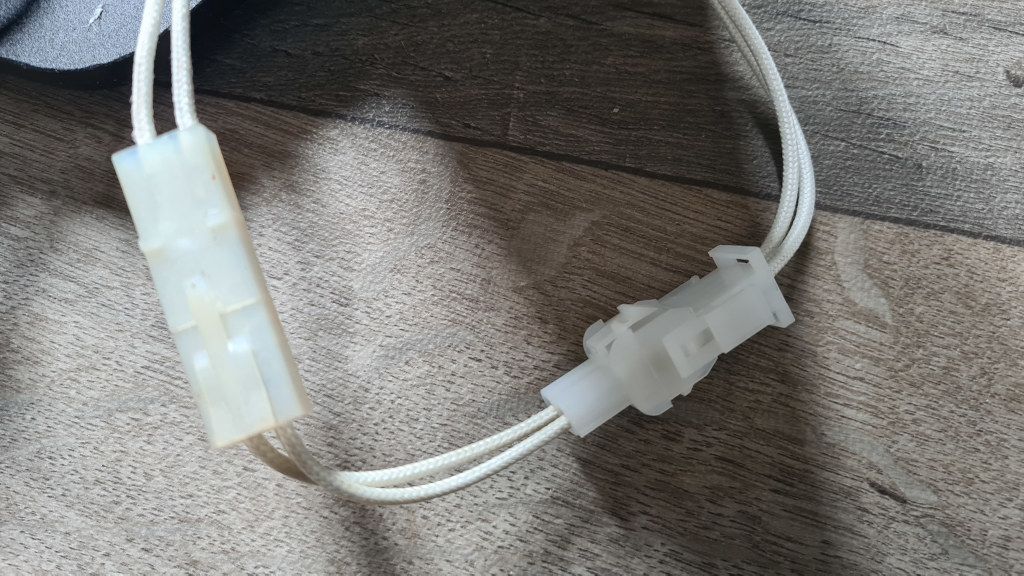
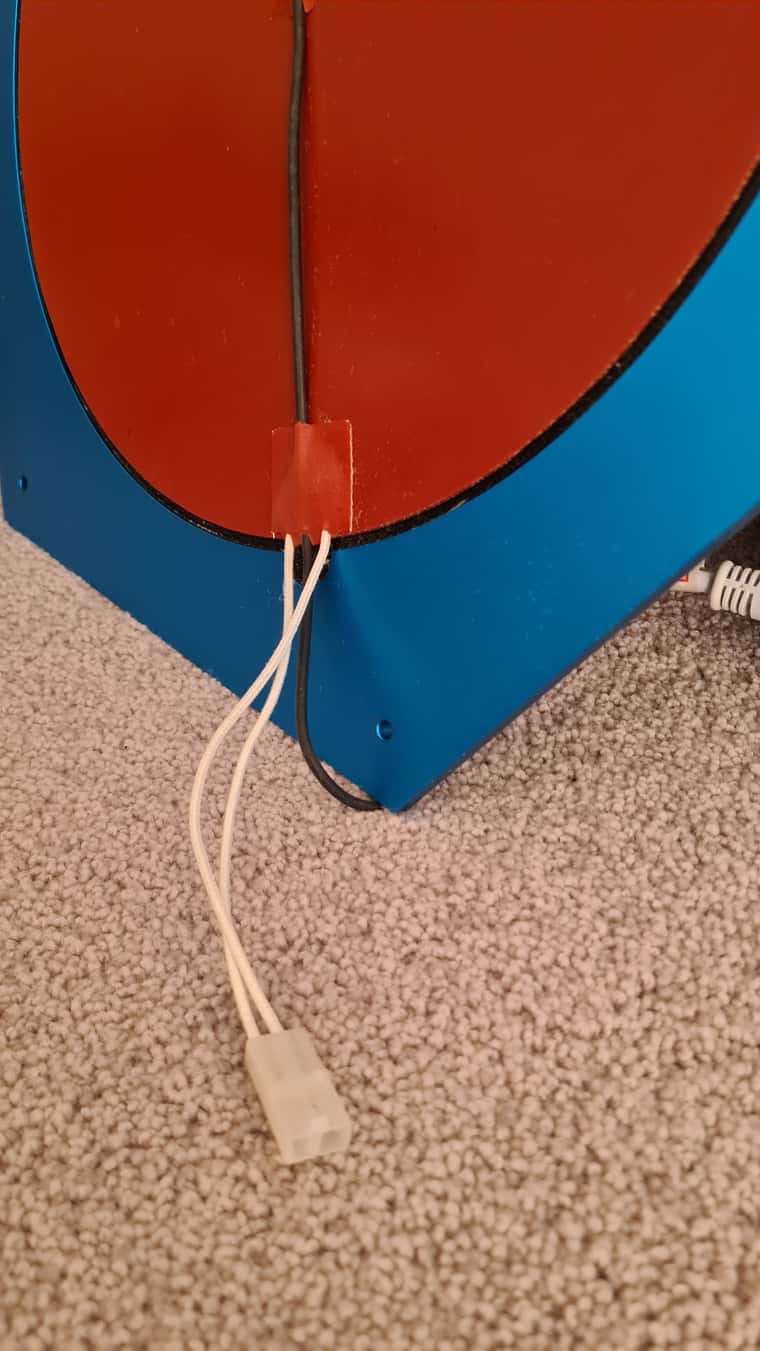
My Google-Fu is failing me. Does anyone have an idea of what connector this is in the photo? My measurement of the pitch is 5.9mm (difficult to measure exactly as it's only 2-way).
For the whole story, I have a Tevo Little Monster delta where I have lengthened the rails. So now I have to lengthen all the cables. For the (mains powered) bed I'd rather build a complete new power cable rather than splice the old one. I could change to a different connector and be done with it, but Ideally I'll keep the original as I have a number of these printers and I'd like the possibility of easily swapping the beds.
@dc42 Thanks for the reply. I took a look at the link, but decided that's quite a departure from the Arduino and would be quite a lot of work to re-implement everything for a new development environment that's otherwise low on my radar. I'll hopefully set up a quick test in the coming days to have a look at the M118 command in more depth.
@droftarts Ahh! I think I might have found something useful - M118.
Eg. M118 P2 S"SET_TEMP 60"
This looks to send the string "SET_TEMP 60" to serial port 2 of the Duet, which I could pick up using the Arduino. Not sure yet how I could send info in the other direction though; like chamber presently at 53C. Or how I could get the Duet to wait until the temperature hits 60.
@droftarts Hmm, having had a look at those two projects as well as generally reading up on PanelDue it looks to me like the Duet sends status information (bed, hotend temperatures etc.) to the PanelDue and the PanelDue sends control information like axis movements to the Duet. So if you're wanting to get in the middle of that, it's all good. I'm not presently seeing how I might use this for a chamber heater interface however. The communication looks to be in the wrong direction, as in the Duet might tell the PanelDue the chamber temperature, not the other way round. Am I missing something?
What I kind of need is a way to see the G-code "as it goes by" to the printer so that I can control the chamber heater. Then somehow to report the chamber temperature back to the Duet. Hmm...