@T3P3Tony
the altered firmware from DC42 seems to be working perfectly.
thanks!
I will report back when we run our first tests of printing 510 phosphor bronze from mcmaster.
https://www.mcmaster.com/9668K92/
@T3P3Tony
the altered firmware from DC42 seems to be working perfectly.
thanks!
I will report back when we run our first tests of printing 510 phosphor bronze from mcmaster.
https://www.mcmaster.com/9668K92/
thanks!
is this linked repository available to be directly upgraded to from a networked SBC?
Or should I copy in the firmware folder manually to the SBC and install it from a local directory by including in the sources list for APT?
I have so far been unable to find this particular firmware using APT search.
do you have a preferred way to do this?
all the best,
Michael Lynn
So one of our project members, Shields experiments provided us a thermocouple isolator interposer for the duet thermocouple board.
this allows us to use a thermocouple directly on the tip of the heater with no insulation and no stainless steel ring.
Unfortunately, this also means that our model parameters are once again out of range...
can you point me to the place in the firmware where I can adjust the model parameter range?
I have no fear of finding and modifying it to make this work. 
@OwenD
others have already done this.
https://hackaday.io/project/169412-wire-3d-printer
https://www.digitalalloys.com/
it requires large currents and does not work with glasses or ceramics.
neat process, but will not work for my application unfortunately.
So after taking @dc42 suggestion and raising the temperature limit to 1750C,
the Autotune (at 700 C target temperature and 0.27 pwm limit with Y20) worked and returned parameters:
Heater 1: heating rate 44.460, cooling rate 0.824, dead time 1.70, max PWM 0.27, mode PID, calibrated at 23.6V
Predicted max temperature rise 1918°C
PID parameters: heating P2.4 I0.233 D2.8, steady P2.4 I0.499 D2.8
This seems to be reliable enough given my janky current setup to transfer to the working printhead.
We also characterized the offset temperature from the glowplug tip to the thermocouple y measuring the tip temperature with an identical type K thermocouple.
here is the result
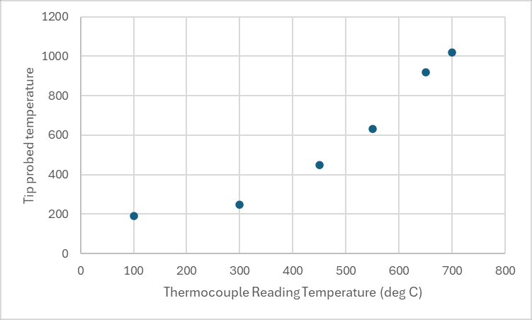
thanks for the guidance. I think this is enough for a start. 
; Configuration file for Duet 3 MB 6HC (firmware version 3.3)
; executed by the firmware on start-up
;
; generated by RepRapFirmware Configuration Tool v3.4.1 on Fri Feb 23 2024 23:32:11 GMT-0600 (Central Standard Time)

; General preferences
G90                                          ; send absolute coordinates...
M83                                          ; ...but relative extruder moves
M550 P"Duet 3"                               ; set printer name
M918 P1 E4 F2000000                          ; configure direct-connect display

; Drives
M569 P0.0 S0                                 ; physical drive 0.0 goes backwards
M569 P0.1 S1                                 ; physical drive 0.1 goes forwards
M569 P0.2 S1                                 ; physical drive 0.2 goes forwards
M569 P0.3 S0                                 ; physical drive 0.3 goes backwards
M584 X0.0 Y0.1 Z0.2 E0.3                     ; set drive mapping
M350 X16 Y16 Z16 E16 I1                      ; configure microstepping with interpolation
M92 X80.00 Y80.00 Z400.00 E93.00             ; set steps per mm
M566 X1200.00 Y1200.00 Z24.00 E300.00        ; set maximum instantaneous speed changes (mm/min)
M203 X9000.00 Y9000.00 Z180.00 E6000.00      ; set maximum speeds (mm/min)
M201 X500.00 Y500.00 Z100.00 E5000.00        ; set accelerations (mm/s^2)
M906 X800 Y800 Z800 E1000 I50                ; set motor currents (mA) and motor idle factor in per cent
M84 S30                                      ; Set idle timeout

; Axis Limits
M208 X0 Y0 Z0 S1                             ; set axis minima
M208 X235 Y235 Z250 S0                       ; set axis maxima

; Endstops
M574 X1 S1 P"io1.in"                         ; configure switch-type (e.g. microswitch) endstop for low end on X via pin io1.in
M574 Y1 S1 P"io2.in"                         ; configure switch-type (e.g. microswitch) endstop for low end on Y via pin io2.in
M574 Z1 S2                                   ; configure Z-probe endstop for low end on Z

; Z-Probe
M950 S0 C"io5.out"                           ; create servo pin 0 for BLTouch
M558 P9 C"io5.in" H5 F120 T6000              ; set Z probe type to bltouch and the dive height + speeds
G31 P500 X0 Y0 Z3                            ; set Z probe trigger value, offset and trigger height
M557 X60:215 Y30:195 S20                     ; define mesh grid

; Heaters
M308 S0 P"temp0" Y"thermistor" T100000 B4092 ; configure sensor 0 as thermistor on pin temp0
M950 H0 C"out0" T0                           ; create bed heater output on out0 and map it to sensor 0
M307 H0 B1 S1.00                             ; enable bang-bang mode for the bed heater and set PWM limit
M140 H0                                      ; map heated bed to heater 0
M143 H0 S150                                 ; set temperature limit for heater 0 to 150C
M308 S1 P"spi.cs0" Y"thermocouple-max31856"  ; configure sensor 1 as thermocouple via CS pin spi.cs1
M950 H1 C"out1" T1                           ; create nozzle heater output on out1 and map it to sensor 1
M307 H1 B0 S0.10                             ; disable bang-bang mode for heater  and set PWM limit
M143 H1 S900                                ; set temperature limit for heater 1 to 900C

; Fans
M950 F0 C"out7" Q500                         ; create fan 0 on pin out7 and set its frequency
M106 P0 S0 H-1                               ; set fan 0 value. Thermostatic control is turned off

; Tools
M563 P0 D0 H1 F0                             ; define tool 0
G10 P0 X0 Y0 Z0                              ; set tool 0 axis offsets
G10 P0 R0 S0                                 ; set initial tool 0 active and standby temperatures to 0C

; Custom settings are not defined

; Miscellaneous
M501                                         ; load saved parameters from non-volatile memory
T0                                           ; select first tool
I have set the temperature limit to 900 C.
why would there be a minimum limit for the model parameters to be accepted?
my heater cannot be allowed to operate above about 1300 C in air for an extended period, or its resistance will drift.
I set a lower limit, because the thermocouple has a large offset temperature and I dont know it exactly. so I set a conservative limit, as I wanted to avoid destroying my heater.
@dc42
I have successfully upgraded to RRF 3.5.0-rc.3.
Autotuning of my heater still fails with the warning
running M303 H1 Y20 P0.27 S750 returns:
"Autotune failed due to bad curve fit (R=53.131 K=0.801:0.000 D=1.25)
If i then take the provided model parameters, and plug them into M307 as:
M307 H1 R53.131 K0.801 D1.25
this command returns
Error M307 : Bad model parameters.
The autotune makes a very nice curve, see picture here:
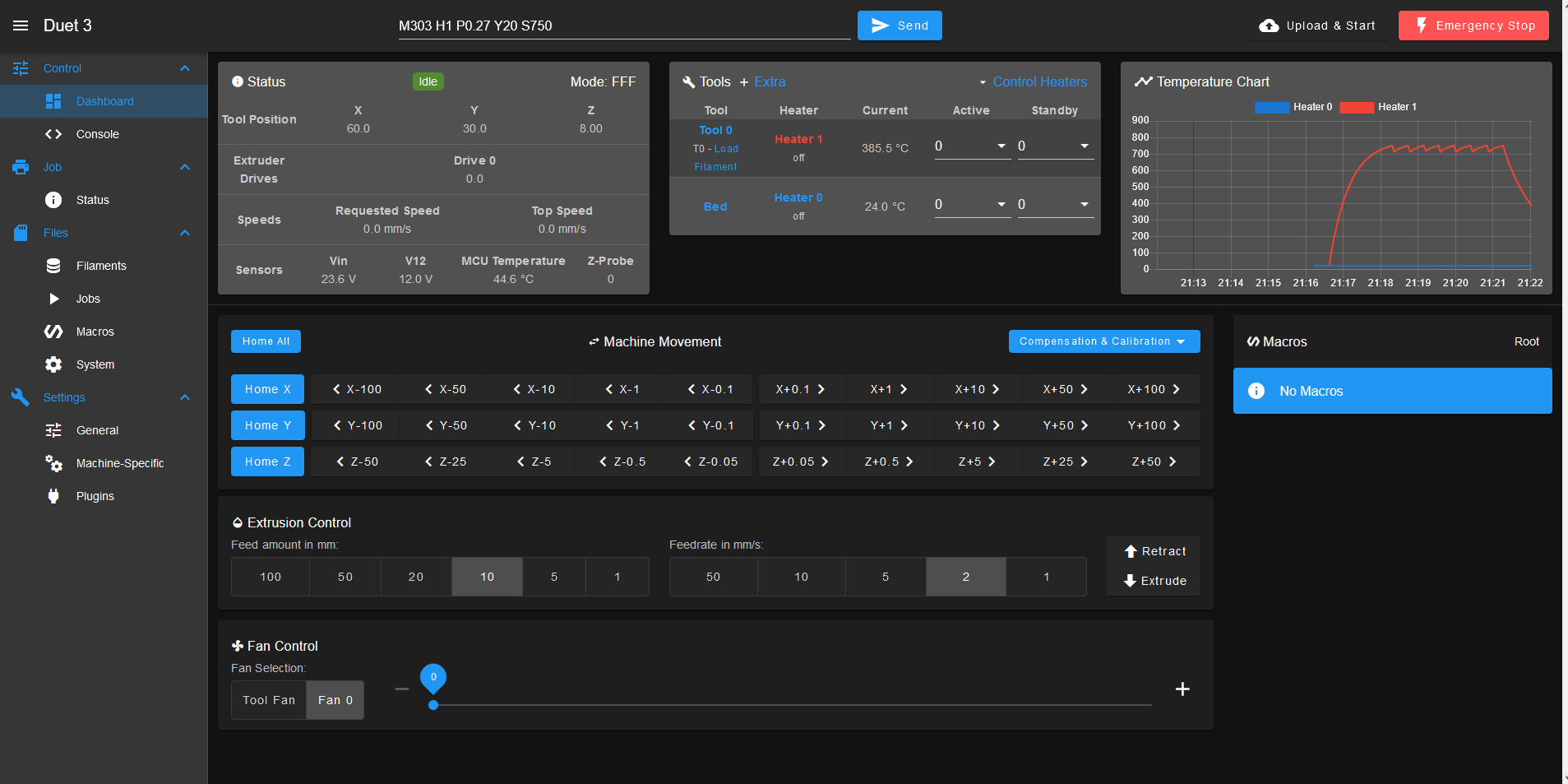
Not sure what to make of this.
@lynnmt
is this an unstable package release?
also,
will the instructions here be sufficient for making this firmware update or are there other sources to consider?
https://docs.duet3d.com/User_manual/Machine_configuration/DSF_RPi#software-installation
when I run the commands suggested for upgrading to unstable releases, here:
sudo rm -f /etc/apt/sources.list.d/duet3d.list
sudo bash -c "echo 'deb https://pkg.duet3d.com/ unstable armv7' > /etc/apt/sources.list.d/duet3d-unstable.list"
my command prompt on SBC returns
bash - "permision denied"
@dc42
excellent. Thanks for running the test.
I will try the upgraded firmware.
A further question,
is there some way to know what these heater limits are and to make them user adjustable without needing to compile firmware?
all the best,
Michael Lynn
@lynnmt Ah! I forgot to mention a important detail!
the glowplug heater is PTC!
@dc42 I am working on making the sensor response even faster.
so I would expect the limits to need to be substantially wider even than those determined by the autotune.
in practice, making up for sensor delay in a system like this is going to be a huge problem. 
Thanks for taking a look!
I will be in touch here and on the discord!
@dc42
if it helps here are some more hardware shots...
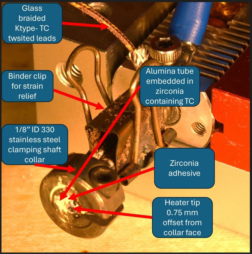
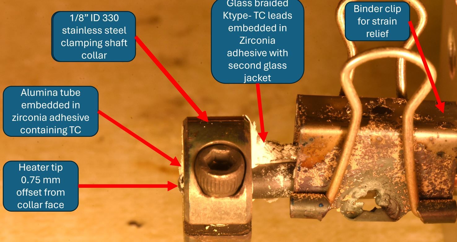
@dc42
I would also mention that it is not the heater it is the thermocouple whose temperature is below the setpoint at the output power due to all the insulation around the Thermocouple.
the heater itself is glowing white hot.
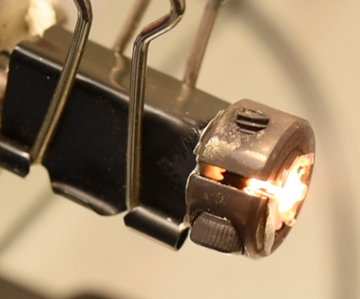
here is a picture of the setup. the thermocouple is inside a 0.05" OD aluminum oxide sheath inside the stainless steel ring, pasted on with zirconia paste as close as possible to the heater.
as requested.
seems to provide the same error with model parameters:
"Auto tune of heater 1 failed due to bad curve fit (R=70.881 K=1.071:0.000 D=1.08)"
what does this mean?
some images....the first is the requested screen capture.
this last tune I screep caped had this warning:
"Auto tune of heater 1 failed due to bad curve fit (R=61.202 K=0.807:0.000 D=1.59)"
@dc42
"Auto tune of heater 1 failed due to bad curve fit (R=89.617 K=0.929:0.000 D=1.16)"
@dc42
any thoughts on how one should tune the Y parameter to adjust for a very fast thermal response rate?
the heater does actually respond at 1000 C /second while heating up, and about 300 per second when cooling down in still ambient air.
After attempting an autotune with the following command:
M303 H1 P0.2 S800,
the autotune fails due to poor curve fit, though the heater does ramp to the target temperature and oscillate around the target set point.
I do get some leakage to the thermocouple due to temperature induced thermal conductivity in the ceramic insulator around it I believe.
@soare0
Thanks for the sage suggestion and the link. 
Thermal capacitance increases are highly undesirable, because they have to be quite large to be meaningful given the density and thermal conductivity of the semisolid metals... metals are excellent coolants.
this also means that most thermal capacitors will "quench" at the interface with the flowing metal, and this causes local granular jamming, and sometimes, outright freezing of the feedstock.
It is critically important that the heater(and sensing and control system) be fast, and responsive enough to dynamically adjust for the phase changes in the material.
for pure copper the window is barely 1/10 of a degree C wide . any thermal capacitor would need to be made of diamond or the like in order to not locally quench the feedstock into the frozen state at standard FDM printing speeds.
Thus, I have resolved this problem by placing the heat source exactly inside the deposition region, in direct contact with the metal at all times. The heat source being made of a hard, ultrarefractory electroceramic of a relatively large thermal conductivity (about 80-120 w/m*k)
I understand that the thermal capacitance may simplify control. but the materials I am trying to print will not tolerate such simplification in any way that does not also make the printhead a huge mass, and temperature gradient constrained to low flowrates. 
I am not the first to attempt this project, the others who have tried, have all done as you suggested and encountered very difficult granular jamming and very slow extrusion performance mostly due (as far as I can tell from interviewing them and doing my own experiments) to large thermal gradients caused by a reliance on excess thermal mass and a heater from the load:
https://hackaday.io/project/179846-semisolid-metal-printing
https://par.nsf.gov/servlets/purl/10351861
https://link.springer.com/article/10.1007/s00170-017-1058-7
The problems they have encountered get worse as temperatures rise toward useful metal printing temperatures, like bronze 510 at ~975 C. higher temperatures mean higher radiative losses and steeper gradients still. More importantly, most thermal mass materials will react with the semisolid metals and will be erroded thereby, thus, you then need some sort of protective lining, which adds more insulation, and so on. this problem spiral quickly out of hand.
hopefully this provides a bit more transparency into the logic of the situation.
@T3P3Tony
I have upgraded to RRF 3.4.6. and the model parameters seem to have taken without issue.
Do i still need to go all the way to RRF 3.5rc3?
I have not yet run an autotune.
I am trying to understand a critical detail first:
does the PWM limit set in the M303 autotuning command override the PWM limit set in the model parameters?
also the M307 H1; command returns now :
M307 H1 ;
Heater 1: heating rate 1000.000, cooling rate 300.000, dead time 0.10, max PWM 0.15, mode PID, calibrated at 24.0V
Predicted max temperature rise 243°C
PID parameters: heating P1.8 I9.297 D0.1, steady P1.8 I11.300 D0.1
@dc42
after upgrading the firmware from the SBC per these posts and docs:
https://forum.duet3d.com/topic/29125/update-1hcl-firmware-from-sbc/3
https://docs.duet3d.com/User_manual/Machine_configuration/SBC_setup
the model parameters seem to have taken.
Thanks for the guidance.
I will try an autotune with the new parameters and report back hopefully with some video footage of the test.