@phaedrux
Thank you for your help!
The start.g attached to my first post is from a friend of mine. He owns the same printer. It is working for him. When I apply the following start.g (the "official" from caribou3d) the first layer is the same:
start.g
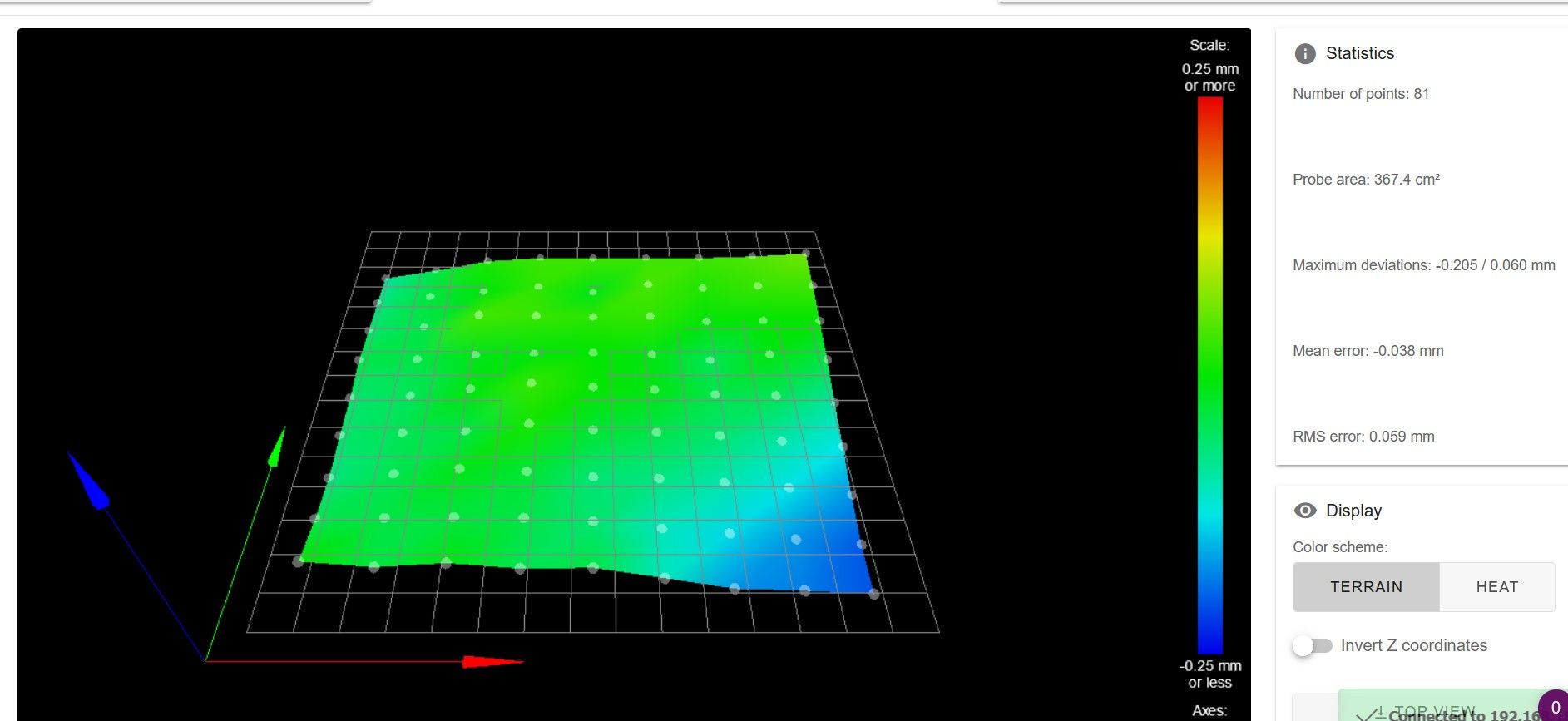
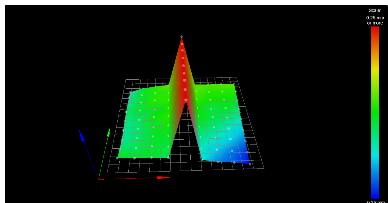
Picture of my heightmap.csv in the systemsfolder (9x9):

gcode-file I try to print (same result when I use prusa slicer 2.3):
; generated by PrusaSlicer 2.4.0+win64 on 2021-12-30 at 16:47:56 UTC
;
; external perimeters extrusion width = 0.60mm
; perimeters extrusion width = 0.50mm
; infill extrusion width = 0.50mm
; solid infill extrusion width = 0.50mm
; top infill extrusion width = 0.45mm
; first layer extrusion width = 0.42mm
M107
;TYPE:Custom
; =========================================================================================================
;
; start script for PrusaSlicer for CaribouDuet
;
; =========================================================================================================
;
G28 ; home all axis without mesh bed level
G0 X60 Y-3 Z80 ; move extruder above bed, keep extruder in front for cleaning and checking
;
M104 S160 T0 ; pre-heat extruder to 160°C
M140 S60 ; this will take the layer 1 temperature for bed 0
M190 S60 ; wait for bed temp
;
G29 ; mesh bed leveling using defined mesh grid
G0 X0 Y-3 Z0.6 ; go outside print area
;
M104 S215 ; set extruder temperature
M109 S215 ; wait for extruder temp
;
; =========================================================================================================
;
;
M98 P"0:/sys/primeLine.g" ; execute primeline macro
;
G92 E0.0 ; set extruder position
;
M572 D0 S0.07 ; set pressure advance
;
; =========================================================================================================
G21 ; set units to millimeters
G90 ; use absolute coordinates
M83 ; use relative distances for extrusion
M900 K0.05 ; Filament gcode LA 1.5
M900 K30 ; Filament gcode LA 1.0
M107
;LAYER_CHANGE
;Z:0.2
;HEIGHT:0.2
;BEFORE_LAYER_CHANGE
G92 E0.0
;0.2
G1 E-.4 F2100
G1 Z.4 F10800
;AFTER_LAYER_CHANGE
;0.2
G1 X4.516 Y7.168
G1 Z.2
G1 E.4 F2100
M204 P1000
;TYPE:Skirt/Brim
;WIDTH:0.42
G1 F1200
G1 X5.452 Y6.976 E.02998
G1 X245.296 Y6.928 E7.52013
G1 X246.603 Y7.32 E.04278
G1 X247.48 Y8.365 E.04278
G1 X247.673 Y9.305 E.03008
G1 X247.673 Y49.309 E1.25429
G1 X247.426 Y201.94 E4.78564
G1 X247.032 Y203.246 E.04278
G1 X245.985 Y204.121 E.04278
G1 X245.051 Y204.313 E.0299
G1 X5.274 Y204.483 E7.51806
G1 X3.967 Y204.092 E.04278
G1 X3.09 Y203.046 E.04278
G1 X2.896 Y202.106 E.03008
G1 X3.076 Y9.35 E6.04373
G1 X3.469 Y8.044 E.04278
G1 X4.47 Y7.207 E.0409
; printing object Form-Kubus id:0 copy 3
for my taste (taste because I am a noob and have no knowledge  ) the g29 Sxx is applied a little to often. Is there any known interference?
I have often read that possibly the z-Motors don't get enough voltage for mesh compensation?
I have already checked that my extruder can travel along the gentry easily. A tilt of the gantry can be performed easily by turning one spindle.
I have not found any further (gcode-)commands where the used mesh can be visualised? Is there a way? Or is there a way to easily visualize the motor signals? So that one can see if there is a signal for the motor to turn?
...and again thank you for your much appreciated help in advance!


 ) the g29 Sxx is applied a little to often. Is there any known interference?