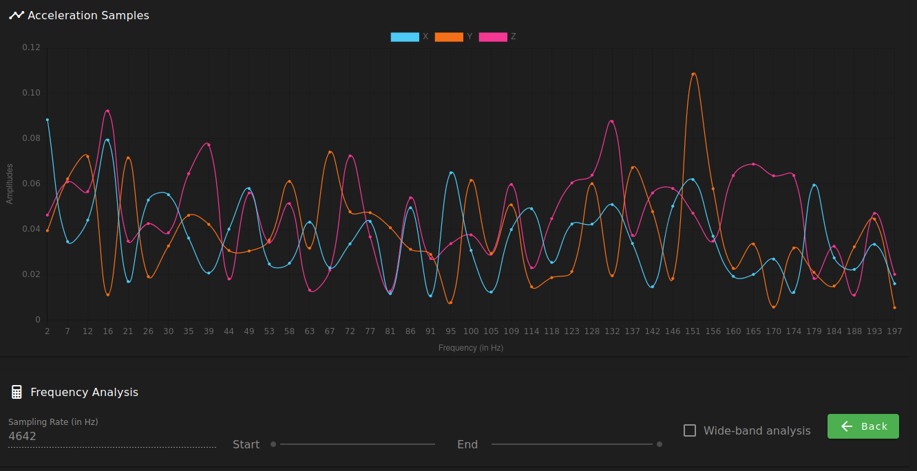
Replaced the sleeve cable with a cat5e ethernet one and now it works.
Graph is all over the place but it works.

Replaced the sleeve cable with a cat5e ethernet one and now it works.
Graph is all over the place but it works.

@phaedrux I'll try that but the current cable length is just long enough for operation. I'll test with a cat5e ethernet cable.
I have connected my accelerometer board successfully but can't get a reading from it.
RRF Version: 3.4.1
Boards: Duet2 Wifi, Duex5
Accelerometer: type LIS3DSH 16-bit resolution, SPI frequency 2000000
Configured it with
M955 P0 C"duex.cs6+spi.cs4" M955 P0

# Console:
M955 P0 C"duex.cs6+spi.cs4" M955 P0
Accelerometer 0 type LIS3DSH with orientation 6 samples at 1600Hz with 16-bit resolution, SPI frequency 2000000
Issue #1: Can't get readings from accelerometer
Connected the CS with a separate wire to duex.cs6 to avoid interference. But when I tried testing it with:
G90 G1 X130 G1 X180 G4 S2 M956 P0 S1000 A0 G4 P10 G1 X130 F20000
The resulting CSV is written as:
Sample,X,Y,Z
Failed to collect data from accelerometer
Then I tried changing it's configuration to the recommended 10 bit resolution, 1344Hz sampling rate, which led me to the second issue...
Issue #2: The M955 R and S parameters are ignored
M955 P0 C"duex.cs6+spi.cs4" I06 S1344 R10 M955 P0

# Console:
# Ignores the S and R new settings
M955 P0 C"duex.cs6+spi.cs4" I06 S1344 R10 M955 P0
Accelerometer 0 type LIS3DSH with orientation 6 samples at 1600Hz with 16-bit resolution, SPI frequency 2000000
Then I tried changing the Q parameter and it's accepted:
M955 P0 C"duex.cs6+spi.cs4" I06 S1344 Q1000000 M955 P0

# Console:
M955 P0 C"duex.cs6+spi.cs4" I06 S1344 Q1000000 M955 P0
Accelerometer 0 type LIS3DSH with orientation 6 samples at 1600Hz with 16-bit resolution, SPI frequency 1000000
I've already checked every connector for signal continuity and every pin source/destination twice. The cable 2m long sleeve with 10 cables in it.
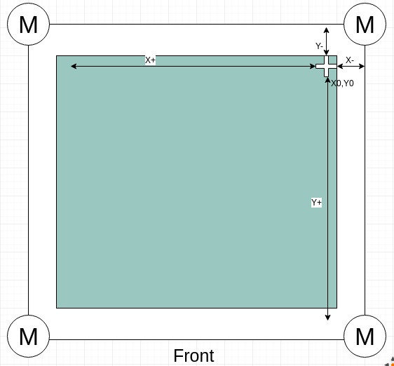
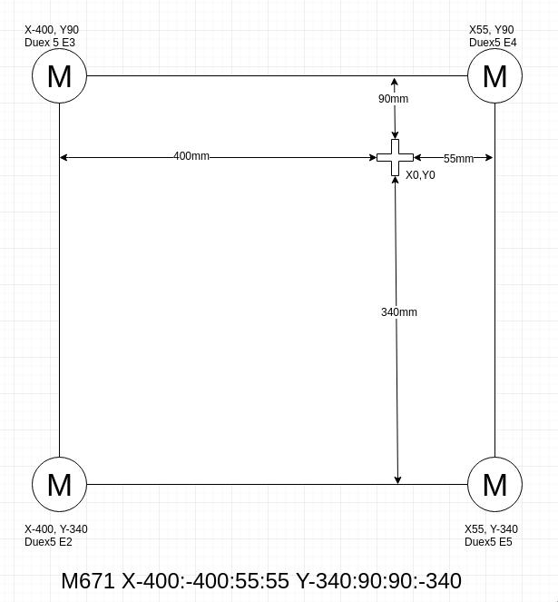
Then, the right motors' coordinates should be:

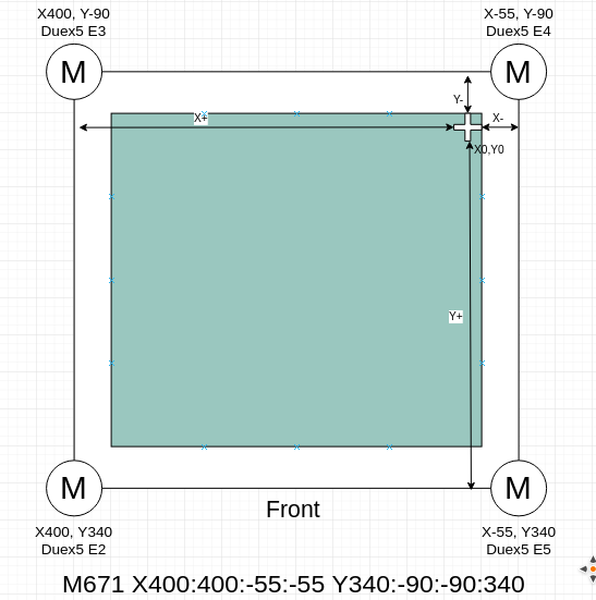
@Danal These are my printer coordinates. I have defined the M671 coords based on the X0,Y0 point. Now I see what I've got wrong about the signals.

@Danal Like this? The distance was measured according to your description about the pivot point (in my case the center of the belts)
The resulting gcode is at the bottom, considering the sequence that the motors are connected to the Duex5

I'm adjusting the M671 command for my Voron 2.1 printer and I just can't figure out what's the reference point for the motor's positions.
Is it the nozzle at Z0? Is it the nozzle at homed position of the gantry (which, in my case, it's a negative value being the 0,0 the back right corner)?
I've replaced the U2 voltage regulator of my Duet2 board but the component is still outputting 0.3v and works fine using an Arduino on the 3.3v rail, as recommended.
How can I diagnose the C4 capacitor of the 3.3v regulation system?
@bearer Yeah, I have a presentation to write right now but I'll do a full test, connecting the board to my Voron. If the processor is alive, it's a great thing already. I'll start replacing U2 (no pun intended).
God, I'm so relieved!
What component is the regulator I must replace? I've been wandering around the KiCad project but I'm a real noob at this
@bearer Excellent idea!
Did this and now the Duet2 board is detected by the OS and I can connect to it using Pronterface. Should I try inserting the SD card now?
Bus 001 Device 022: ID 1d50:60ec OpenMoko, Inc. Duet 3D Printer Controller
My room temp is about 25C but no component is above 31C. Checked the wifi module, U11, U2, steppers, processor... Nothing seems out of the ordinary. I believe the U11 is the 3.3v regulator.
Unfortunately I don't have a 3.3 ext PSU.
@bearer said in Diagnosing a probably bricked Duet2:
U2? Which Duet 2 do you have?
But yeah, if the voltage regulators aren't doing their job then I'd start by removing the regulator, measure the impedance on the regulators output pads (i.e. on the board) and possibly feed in power from a current limited bench supply to see what else may or may not heat up, and keep removing parts until you have a nominal current draw, then start soldering in replacements.
Sorry, it's a Duet2 1.04b
@dc42 said in Diagnosing a probably bricked Duet2:
At the vert least the WiFi module and the SD card will have failed.
Yes, the Wifi module does not light up it's blue led.
@dc42 said in Diagnosing a probably bricked Duet2:
Probably also the 3.3V regulator and the processor.
Is there a way I can test this while powered to VIN 24v or USB, before I try the external 3.3v PSU?
Hi, this is my first post and I'd like to announce that I probably scored an 8/10 on the "how to destroy you Duet2" guide. I managed to misplace one z probe wire and shorted it with the heater. The board lighted up as if it was Christmas and quickly I disconnected it from power (24v).
Now, when I connect the board to my desktop via USB, only the 5v and USB power leds light up and the board is not detected by the computer's OS. I have followed all the steps in the wiki, nothing worked.
I have a moderate knowledge in electronics and started to diagnose the board. The first thing I found out is that, when connected to the USB power, the U2 regulator is outputting 0.55v to the 3.3v rail and the 3.3v pin of the z probe has the same voltage reading. When the power comes from VIN 24v, the z probe connector 3.3v pin reads 0.68v. There is no reading on the U2 pins.
I'd like to know if I should replace the U2 regulator or if there are any further steps that I should follow to get the correct diagnose of my board's problem.
Thanks in advance