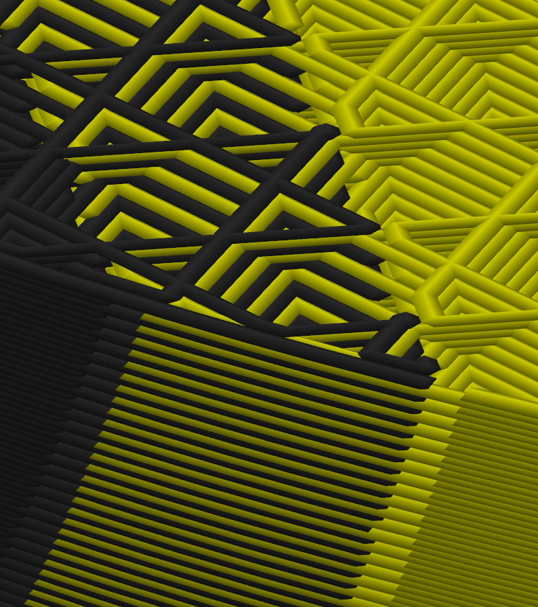
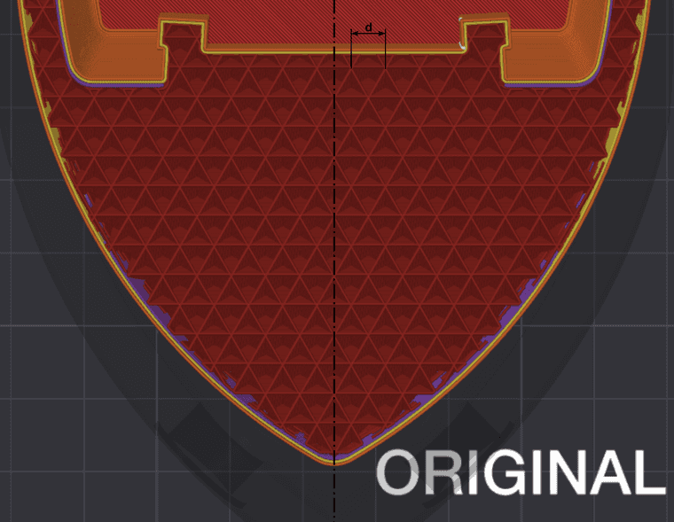
@dwuk This is not quite what I meant. I meant a interlacing pattern, wide enougth to weld together the sparse infill: 
This way you should retain close to full part strength and can put all perimeters in a single thread for optimal surface quality. Scince the sparse infill appears to be generated in relation to a global origin, this should work for arbitrary models and infill patterns when in parallel printing mode. For parallel mirror mode, you need a infill pattern that is and stays symmetrical to your mirror plane regardless of z-height. From the more performant infill patterns, cubic appears to work, when angle is changed to zero:
You can ignore the d-dimension. I dont know why I thought having the interlacing that wide would have been critical. I put my files on a printabels site, if you want to take a look, but cant post the link here due to lack of reputation. Ill put it in a Youtube comment for now.
Best posts made by JVan
-
RE: IDEX BOTH ON CORE XYposted in MultiAxis Printing
-
RE: IDEX BOTH ON CORE XYposted in MultiAxis Printing
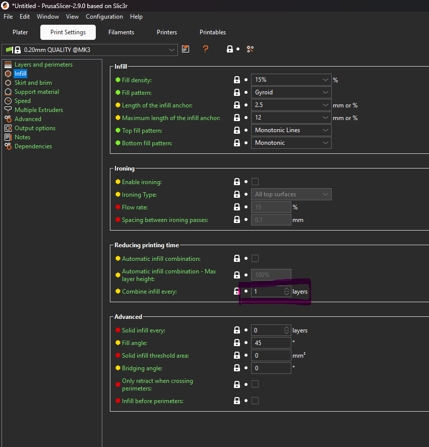
@dwuk Its this setting. Setting it to 2 will result in double height infill lines:

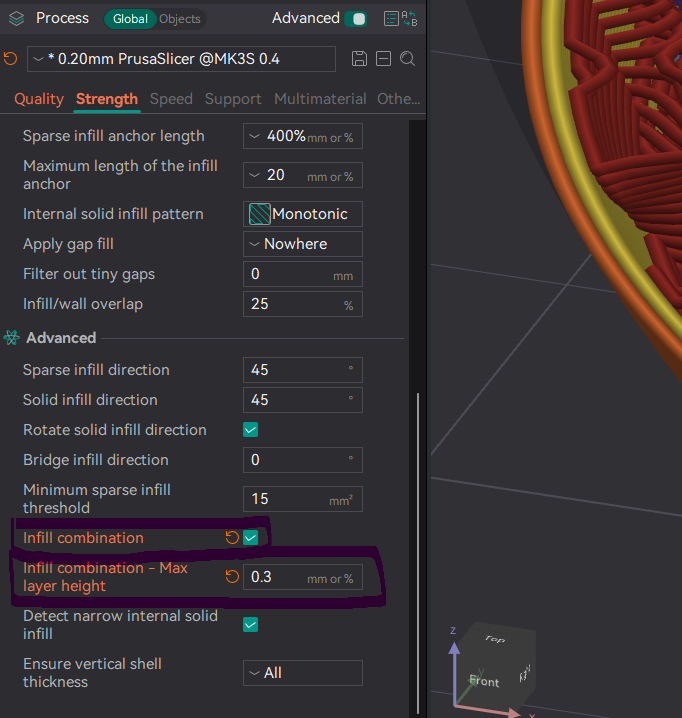
On Orca and (probably) Bambu its this. Here you set infill layer heigth directly. Either as mm or as % times nozzle diameter:

Latest posts made by JVan
-
RE: IDEX BOTH ON CORE XYposted in MultiAxis Printing
@dwuk I have a question regarding your segment width: From your last screenshot I guestimated in relation to your buildplate grid, that your minimal segment width is about 20mm. If I undestand correctly, you print every other segment simultaniously (like darker grey, green, red and blue) and then switch to the other half of the segments (the white ones) to ideally never have to park a gantry. My question would be, if those 20mm are a realistic assumption: If you have only two gantries, you can probably design a extruder, that has the nozzle axis quite close to one side (like the J1 Extruders but rotated), allowing you to put the nozzle axis planes of two gantrys about 20mm apart with additional hardware sticking out further to the front and the back. But if you have more then two gantries, the whole gantry width is relevant including aluminum profile, linear rail and carriage, motor, fan etc ... So, do I misunderstand something, are you using stand in values or is the buildplate texture differently scaled?
-
RE: IDEX BOTH ON CORE XYposted in MultiAxis Printing
@dwuk Its this setting. Setting it to 2 will result in double height infill lines:

On Orca and (probably) Bambu its this. Here you set infill layer heigth directly. Either as mm or as % times nozzle diameter:

-
RE: IDEX BOTH ON CORE XYposted in MultiAxis Printing
@dwuk This is not quite what I meant. I meant a interlacing pattern, wide enougth to weld together the sparse infill:

This way you should retain close to full part strength and can put all perimeters in a single thread for optimal surface quality. Scince the sparse infill appears to be generated in relation to a global origin, this should work for arbitrary models and infill patterns when in parallel printing mode. For parallel mirror mode, you need a infill pattern that is and stays symmetrical to your mirror plane regardless of z-height. From the more performant infill patterns, cubic appears to work, when angle is changed to zero:
You can ignore the d-dimension. I dont know why I thought having the interlacing that wide would have been critical. I put my files on a printabels site, if you want to take a look, but cant post the link here due to lack of reputation. Ill put it in a Youtube comment for now.