OOh.. damn.. I see.. a tools without filament didn´t work...
So after I set a Filament at the 3rd extruder.. it works...
So.. now the first really Testprint
Now I strugeling with wraping.. . I think thats only a question of time.. to solve this too.
I start with 3D printing since 2016 with a CTC Bizer 1.. works well up to something blow up the board.
last year a bought a Trovxy X5s.. stock.. and build it up.. a short time it work´s.. not good .. but for 230 bucks..it´s ok.
So I redesign my Tronxy..: 4 Linearrails in each corner with complete 15mm Aluminum Carrier for the bigger Bed (350x350), a new silicon-Bed-Heater 600W with it´s own powersupply.
Spend two beltdriven new ball screw double ancor Z-Axis with one stepper.
A heater with triple input (3 Extruders). I also change the X-Axis with the Extruder to an Linearrail
And last but not least.. a new Duet 2 WiFi 1.04 + a BLTouch + Duex5
OOh.. damn.. I see.. a tools without filament didn´t work...
So after I set a Filament at the 3rd extruder.. it works...
So.. now the first really Testprint
Now I strugeling with wraping.. . I think thats only a question of time.. to solve this too.
Hi, I don´t know if it helpfull. But here the interesting config part.
; Mapping of Driver for X,Y, Z1-3, E1-3
M584 X0 Y1 Z5:6:7 E3:4:8 ; three Z motors connected to driver outputs 5, 6 and 7 (U,V,W), driver 8 for E2
M667 S1
; BLTouch - Heater 7
M307 H7 A-1 C-1 D-1 ; Disable heater 7 to free up PWM channel 5 on the Duex board.
; BLTouch - FAN2 Ch 22
;M106 P2 I-1 ; Disable Fan2 Duet to free up PWM channel 22 on the Duet board.
; Define the X and Y coordinates of the leadscrews.
M671 X8:360:162 Y370:370:5 S3
; Drives
M569 P0 S0 ; Drive 0 goes backwards X
M569 P1 S0 ; Drive 1 goes backwards Y
M569 P3 S0 ; Drive 3 goes backwards E0 (E1)
M569 P4 S0 ; Drive 4 goes backwards E1 (E2)
M569 P5 S0 ; Drive 5 goes backwards Z1/U
M569 P6 S0 ; Drive 6 goes backwards Z2 V
M569 P7 S0 ; Drive 7 goes backwards Z3 W
M569 P8 S0 ; Drive 8 goes backwards E2
M350 X16 Y16 Z16:16:16 E16:16:16 I1 ; Configure microstepping with interpolation
M92 X80 Y80 Z800:800:800 E97.24:97.24:97.24 ; Set steps per mm
M566 X900 Y900 Z20:20:20 E990:990:990 ; Set maximum instantaneous speed changes (mm/min)
M203 X12000 Y12000 Z800:800:800 E1600:1600:1600 ; Set maximum speeds (mm/min)
M201 X500 Y500 Z400:400:400 E900:900:900 ; Set accelerations (mm/s^2)
M906 X950 Y950 Z1200:1200:1200 E990:990:990 I30 ; Set motor currents (mA) and motor idle factor in per cent
M84 S30
; Axis Limits
M208 X0 Y0 Z0 S1 ; Set axis minima
M208 X370 Y370 Z430 S0 ; Set axis maxima
; Endstops
M574 X1 Y2 S1 ; Set X=low end Y= high end active high endstops
; Z-Probe
M574 Z1 S2 ; Define Z1 to use Probe at low End. Home to Min. S2 = Z probe
; Depending on wich connection for BL-Touch is used
M558 P9 H7 F500 T9000 X0 Y0 Z1 ; Set Z probe type 5 to bltouch (P5 as Betrue3D) and the heater (7) height + speeds (+ B1)
G31 P25 X+25.7 Y+3 Z 1.471 ; <- <- <- Set Z probe trigger value (1-25, not 500), offset and trigger height (3fach-PH noMixing)
M557 X45:325 Y25:325 S30 ; Define mesh grid
I´f checkt it.. and .. Tata... YES.. it´s working now.. Great
Now my BL-Touch is running at PWM5, Heater 7
my Object-FAN is working and the control in Web-Control, a little different as I expected.. but it´s working.
Thanks for the final inspiration with 5V for BLT.
Why? spray it... or get a tape... a injektion with some color.. use a big Edding... etc.
I don´t have the right calculation at the hand now.. but think I know.. .
If you try to extrude 10mm and you have mark the filament at a position for checking how many flament is extrude. So you able to check if your calculation is korrekt.
Or see here in German:
https://www.youtube.com/watch?v=0FLgeU1Ockk
https://drucktipps3d.de/extruder-esteps-kalibrieren/
or in english
https://3daddict.com/3d-printer-extruder-calibration-steps/
https://www.youtube.com/watch?v=LzZZaGmeX8w
https://www.youtube.com/watch?v=YUPfBJz3I6Y
Your Value in S3D.. is the value for the speed of printing. You have the possibility to abjust it at the WEB-Control.
But the max. mechanical possibility´s are only defined at the config.g
If you use a low value in S3D, you get a very fine Print... if your value in S3D high, you get a rough print.. maybe for testing your construction in real.
You should change your values for the Outline-Speed, the innerfill-speed and so on...I have like 40 or 50% of the First value.
Normaly it deepends on your selection, wich quality you would to print.
Ian, I´v learnd a lot bevor from your blog. Special about multicolor and the Diamond Nozzle.
Today, for me it worked not... often it is clogged and I don´t know why... not really.
My Idea, special in mutimaterial printing is... only two materials... but with a very small nozzel.
So the volum at the nozzle inside is extremly minimal.. and so ... perhaps... it´s possible to come like direct injektion.
The 3-diamond nozzle contains whereby the 3 E3D´s more machanical space and therefor more Material.
Equivalent bigger is your 5-Nozzle and so.. more material.
If you thing about how many material come through the small hole in the front of the nozzle... you can imagine, wich impact has a little more volume at the inside.
Thats my Idea for an very, very small Nozzle, with only two E3D and a very compact dimension.
I don´t know if it´s right and if it works... but that my Idea.
Hey Folks... I got it... Play some around... and I fixed both.. my problem with the FAN´s AND the BL-Touch at DUEX5.
My Config.g and some other ".g" Files
homez.g homey.g homex.g homeall.g deployprobe.g config.g bed.g retractprobe.g
My Makros as Textfiles
No more FAN´s with the new Updating FW & DWC
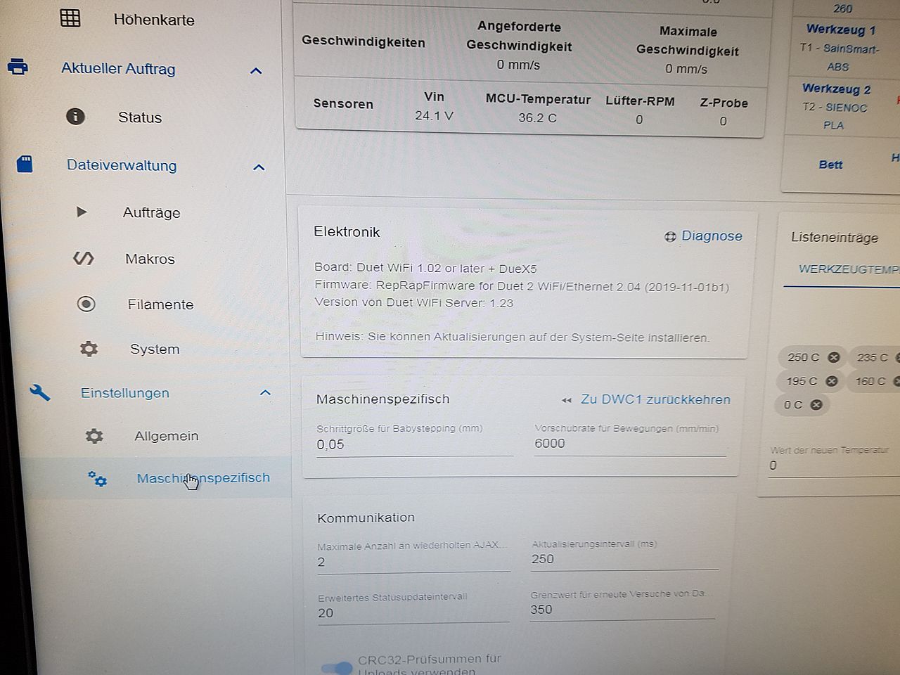
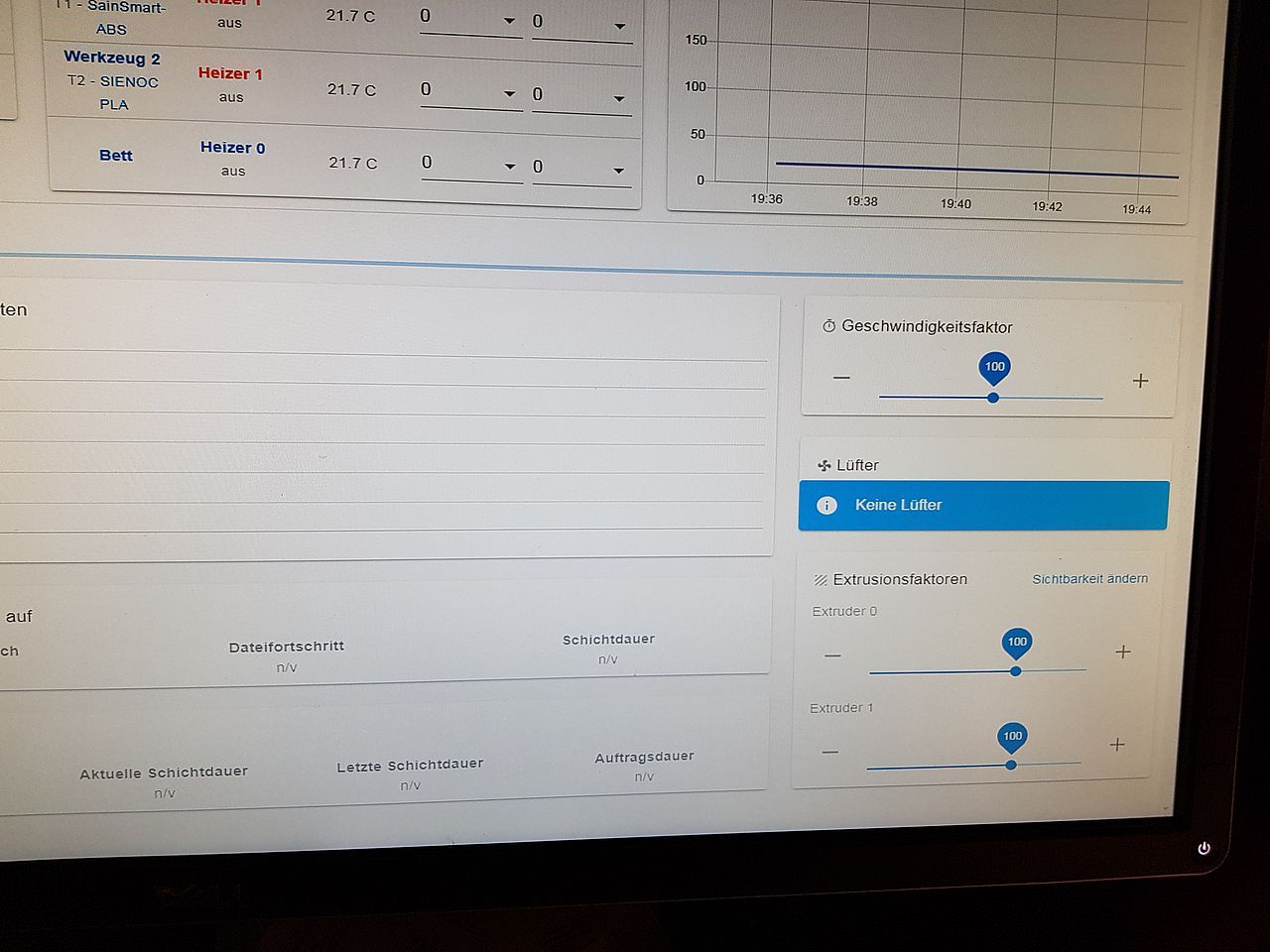
By the way... You can see... Now it´s only 2 extruders there... but I have nothing change at the config of 3 extruders.
Any Hints for me?
my complete Config.g
OK, the visibility of the 3rd Extruder is ok... I have to change the visibility tickmark. So it´s ok now.
But the FAN´s (Lüfter) still nothing. No control.. no visibility.. no possibility.
I´f a similar Problem with FAN´s.
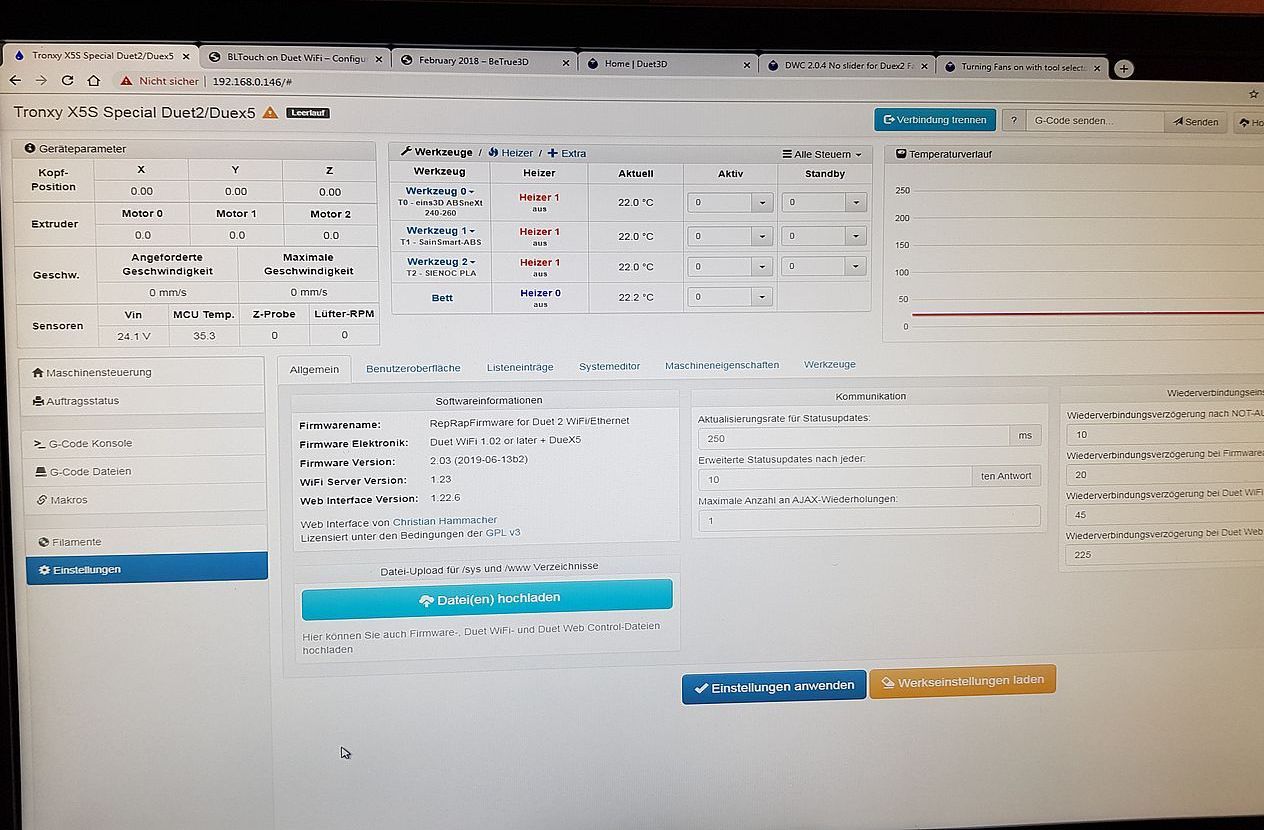
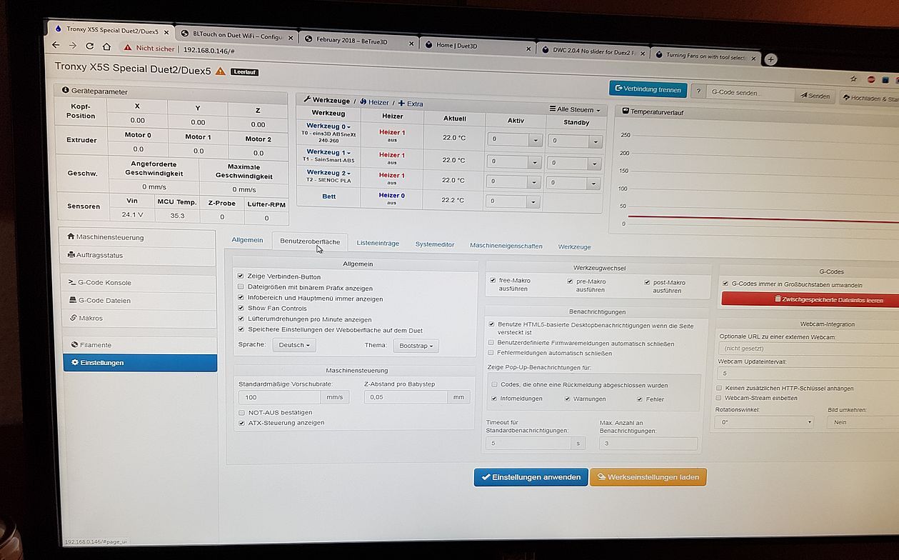
In my case, it´s only shown one FAN after finish with booting.
But a very short time bevore, it is shown correct.
Pic 1 is the very short view at Starttime
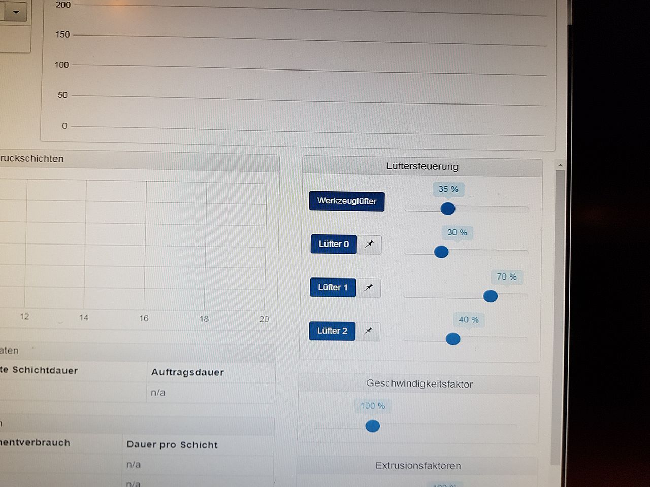
Pic 2 is after finish booting.
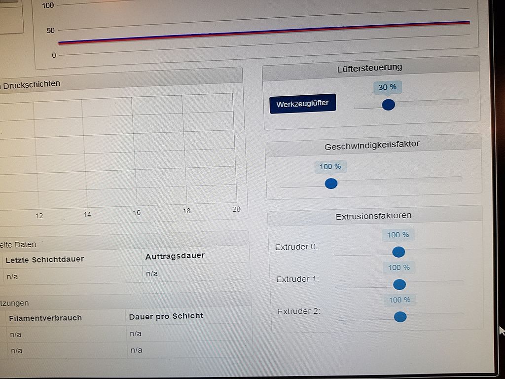
Pics of my enviroment
My relevant Part of Config.g
; Fans
M106 P0 S0.3 I0 F500 H0 T175 C"Objekt-Fan-175" ; Set fan 0 value, PWM signal inversion and frequency. Thermostatic control is turned on
M106 P1 S0.7 I0 F500 H1 T90 C"Tool-Fan-90" ; Set fan 1 value, PWM signal inversion and frequency. Thermostatic control is turned on
M106 P2 S0.4 I0 F500 H0:1 T105 C"Tool-Fan2-90" ; Set fan 2 value, PWM signal inversion and frequency. Thermostatic control is turned on / (off=H-1)
; Tools
M563 P0 D0 H1 ; Define tool 0
G10 P0 X0 Y0 Z0 ; Set tool 0 axis offsets
G10 P0 R0 S0 ; Set initial tool 0 active and standby temperatures to 0C
M563 P1 D1 H1 ; Define tool 1
G10 P1 X0 Y0 Z0 ; Set tool 1 axis offsets
G10 P1 R0 S0 ; Set initial tool 1 active and standby temperatures to 0C
M563 P2 D2 H1 ; Define tool 2
G10 P2 X0 Y0 Z0 ; Set tool 2 axis offsets
G10 P2 R0 S0 ; Set initial tool 2 active and standby temperatures to 0C
Hi Hugo, thanks for this Input, sounds good.
I will check it in the next 2-3 Weeks (some other work).
But great if this would work also for me.
Thanks.
I´ve change my Configuration... like this Betrue3D.dk
Now it works with 3 Z-Axis and Meshkompensation
With my eyes.. perfekt!
If you want my config, let me know.