@droftarts
Thanks !
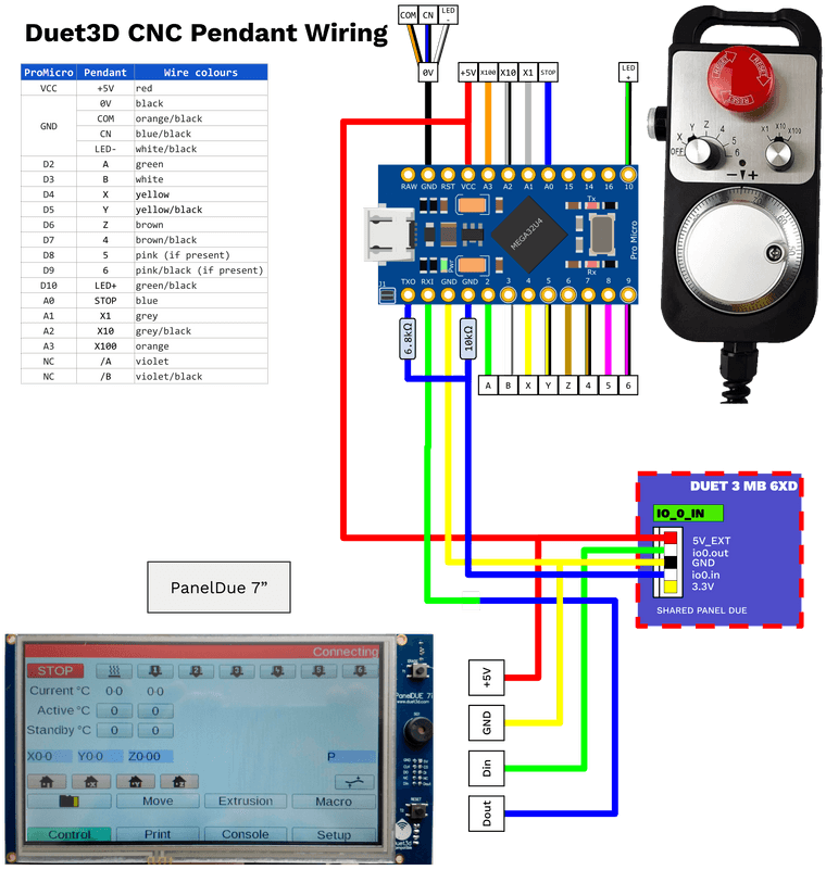
I've just updated the svg : https://drive.google.com/file/d/1mnaXqU4zVAt4ciulPTDM1ZS2i1TMj-y_/view?usp=sharing
Here's the png : 
@droftarts
Thanks !
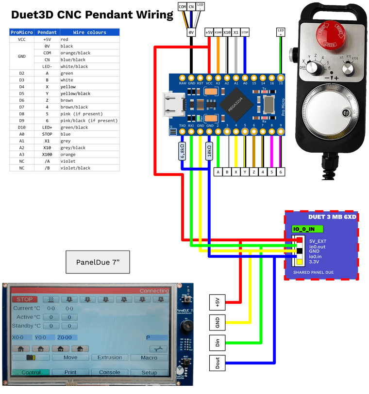
I've just updated the svg : https://drive.google.com/file/d/1mnaXqU4zVAt4ciulPTDM1ZS2i1TMj-y_/view?usp=sharing
Here's the png : 
@droftarts here is the link for the svg : https://drive.google.com/file/d/1mnaXqU4zVAt4ciulPTDM1ZS2i1TMj-y_/view?usp=sharing
Hope everything is good in this schematic
Hi everybody,
I am planning to build a CNC pendant according to this documentation : https://docs.duet3d.com/en/User_manual/Connecting_hardware/IO_CNC_Pendant
I will also use the panelDue.
I have made this schematic after reading the readme and the documentation, could you confirm that this is correct ?
I am not sure about the panel due passthrough.... Don't understand really what is in the actual documentation

Thank you for your answer !
Jeff
PS : If you want the svg to complete the documentation and the github. tell me (after correction if needed  )
)
@dc42 Thank you for your answer.
So for the moment, I will wire the serial port to the IO_1 of the mainboard 6XD as it is working and move my button (in this io for the moment) toward the expansion board. It is not a problem I think.
The commands that I send to the UART are just json data.
The WLED support json API via Serial : https://kno.wled.ge/interfaces/json-api/
JSON over Serial
You can send commands to the WLED instance via Serial using the JSON API.
To request a JSON response containing the state and info objects, send {"v":true}.
for example I send such command :
; TURN ON ALL THE STRIPS
M118 P5 S"{""on"":true}"

;LAUNCH HOMING ANIMATION
M118 P5 S"{""ps"":1}"

; LAUNCH ALERT ANIMATION
M118 P5 S"{""ps"":99}"

; PUT BRIGHTNESS TO 255
M118 P5 S"{""bri"":255}"
Hello.
I am trying to make communication between a wemos ESP board and Duet 3 boards in order to pilot WLED instance directly from GCODE (M118 P5)
I managed to declare a serial connection using the AUX2 UART port on the mainboard 6XD with the command M575 in my config.g file
M575 P2 B115200 S2 ; declare the serial communication between Wemos and Duet 3 EB 3HC on second UART
TX from Duet 6XD on IO_1 (io1.out) wired to the RX pin on the Wemos
And the M118 P5 transfer serial order to my WLED board.
And it is working very well !!!!
Now I would like, instead of using the 6XD mainboard (all the IO are busy), using the IO_1 of the Expansion Board 3HC.
I have read that the IO_1 is UART capable.
But how to set serial comms parameters with the M575 for an expansion Board ?
I have tried M575 P1.2 ... It is not working....
Is-it possible to use an expansion board for that purpose ?
Or do I have to reorganise my wiring to use the mainboard for that ?
Thank you
Jeff
@dc42 Thank you for your answer.
As you suggested, I connect directly the nc output on the IO_IN and it is working very well. No need opto-iso indeed for NPN Proximity sensor
Hello everybody.
I am planning to use an 6XD to drive my CNC with proximity sensor for endstop.
The sensor will be NPN NC 6-36v (i will use 24V).
I think I have to use the opto isolated input (IO_5_ISO_IN --> IO_8_ISO_IN)
In the config.g I will put these lines :
M574 X1 S0 P"!io5.in.iso"              ; X LEFT HOME PROXIMITY SENSOR IO_5 OPTOISO configure switch-type (e.g. microswitch) endstop for low end on X via pin io5.in
M574 Y1 S0 P"!io6.in.iso"              ; Y RIGHT HOME PROXIMITY SENSOR IO_6 OPTOISO configure switch-type (e.g. microswitch) endstop for low end on Y via pin io6.in
M574 Z2 S0 P"!io8.in.iso"              ; Z HOME PROXIMITY SENSOR IO_8 OPTOISO configure switch-type (e.g. microswitch) endstop for low end on Z via pin io7.in
M574 V1 S0 P"!io7.in.iso"              ; Y LEFT HOME PROXIMITY SENSOR IO_7 OPTOISO
And the wiring that I am imaging :

Could you tell me if you are ok with my wiring and config ? I don't want to burn my mainboard 
Thank you !
Already done by T3P3 on github. What a job !!!
Less than one minute to do the job.
Thank you !
https://github.com/Duet3D/Duet3-Mainboard-6XD/blob/master/v1.0/Duet3_MB_6XD_v1.0_Wiring_Diagram.svg
Hi everybody,
I am planning building my CNC with a Duet 3 6XD and I am looking for a SVG format wiring diagram. I have found it for all the boards in the github but not for this particular board.
Any chance to have it ?
Thank you
@wilriker said in Laser Mode, Endstop Limit and Homing:
Your Z position after homing is beyond the configured max of 70
That was it !!
Thank you.
Now without the tool offset. Everything is ok.
I can move freely after homing
I am using DWC and it displays X : 0, Y : 0, Z : 78,25
I have a probe offset for the Z (I'va got to check)
Ok it's a bug but the workaround you explain is usefull only for the homing procedure. In this case, indeed I can homing safely with the M564 S0 / S1 statement.
But after homing, I still have the error ERROR : G0/G1 : outside machine limits if I want to move with the jog interface in DWC. To do so, indeed I have to send the GCODE M564 S0 ; But you're agree with me that's not safe 
It's like the machine boundaries set up with these lines :
; Axis Limits
M208 X0 Y0 Z0 S1                  ; Set axis minima
M208 X857 Y1150 Z70 S0             ; Set axis maxima
are not "compiled" / "understood" in the laser mode ?!?
Ok,
I've just checked :
Change homing files with H1 and H2 paramaters WITHOUT M452 Laser mode :
Everything is OK (as before  ).
).
Add the two lines to activate my laser head in config.g :
; LASER Settings JEFF
M307 H6 A-1 C-1 D-1       ; Disable Heater output on Heater 6
M452 P6 R255 F200         ; Enable Laser mode, on output 6 (heater 6), with max intensity being 255, and a PWM frequency of 200
And then impossible to move after homing : ERROR : G0/G1 : outside machine limits
Tell me if you have an idea
Hello everybody,
I've just finished to setup my cnc with the ethernet board + expansion board (external DM542T drivers).
Everything is ok and now I try to add a laser head in addition of the spindle.

All the wiring is ok and the laser is operational connected the ttl input (+ and -) of the laser module to the heater 6 pwm + gnd of the expansion board.
Add the following line to the config.g to do the job :
; LASER Settings JEFF
M307 H6 A-1 C-1 D-1       ; Disable Heater output on Heater 6
M452 P6 R255 F200         ; Enable Laser mode, on output 6 (heater 6), with max intensity being 255, and a PWM frequency of 200
I mean that entering Gcode M3 S255 trigger the laser and M5 stop it and G1 with S255 fire the laser and G0 no laser.
I have change the homing sequence according to the evolution of Firmware 2.02 in laser mode (replace Sx parameter by Hx)
For example for Z I have got :
G91              ; relative positioning
G1 H1 Z70 F1500 	; move quickly to Z axis endstop and stop there (first pass) - JEFF replace S1 by H1 (LASER MODE)
G1 H2 Z-3 F2400      ; go back a few mm - JEFF add H2 to avoid error G0/G1 outside boundary
G1 H1 Z70 F300 ; move slowly to X axis endstop once more (second pass) - JEFF replace S1 by H1 (LASER MODE)
G90              ; absolute positioning
The problem is that after this and homing, it's impossible to move the head.
Each time I try to move (using DWC jog interface or by GCode command), I've got this error :
Error: G0/G1: outside machine limits
If I disable all the modifications for the laser mode, make homing and after in a macro put in laser mode, I can move.
So, my questions :
config.g and homing file attached :
homez.g
homey.g
homex.g
homeall.g
config.g
Firmware Name: RepRapFirmware for Duet 2 WiFi/Ethernet
Firmware Electronics: Duet Ethernet 1.02 or later
Firmware Version: 2.02(RTOS) (2018-12-24b1)
Web Interface Version: 1.22.6
Thank you for your answers