Hi,
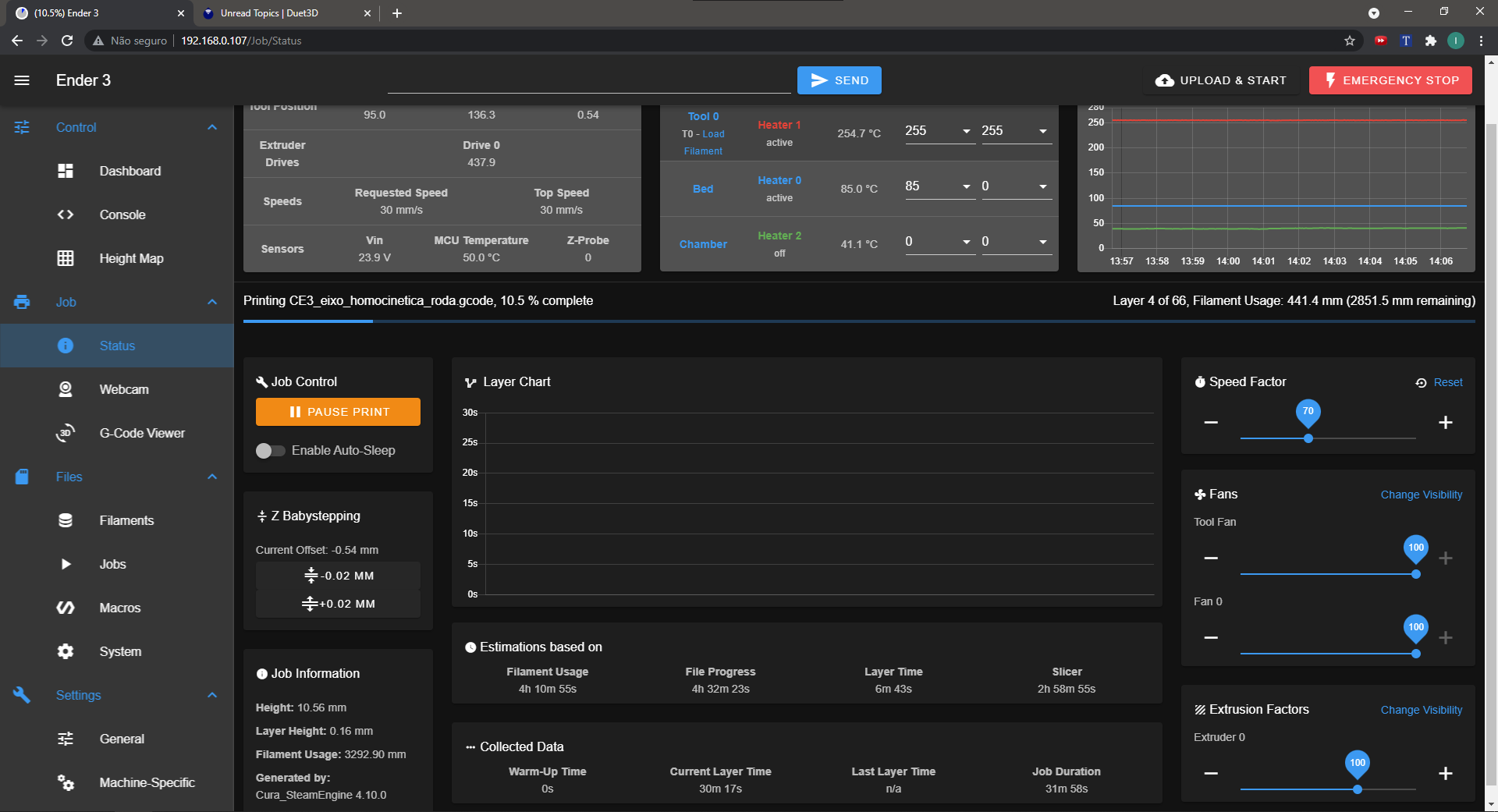
Im relatively new to the duet firmware, and after a couple of months printing with an Ender 3 with duet wifi motherboard, the layer time is no longer working properly. Although it shows the current layer correctly on the progress bar, the last layer time doesn't update, neither does de layer time graph.
For clarification, I'm using cura as slicer, with the reprap gcode flavor and one example gcode is attached (not exactly the gcode from the screenshot because its too big to upload here, but I can upload to my drive if that helps). Also, this is my home routine and config.g files, as I think that maybe this has to do with the BLTouch configuration.
Any help will be apprecieted.
Thanks
; homeall.g
; called to home all axes
;
; generated by RepRapFirmware Configuration Tool v3.2.3 on Fri Jun 25 2021 17:30:43 GMT-0300 (Horário Padrão de Brasília)
G91                     ; relative positioning
G1 H2 Z5 F6000          ; lift Z relative to current position
G1 H1 X-250 Y-245 F3000 ; move quickly to X and Y axis endstops and stop there (first pass)
G1 H2 X5 Y5 F6000       ; go back a few mm
G1 H1 X-250 Y-245 F120  ; move slowly to X and Y axis endstops once more (second pass)
G90                     ; absolute positioning
G1 X122 Y117 F6000        ; go to first bed probe point and home Z
G30                     ; home Z by probing the bed

; Uncomment the following lines to lift Z after probing
;G91                    ; relative positioning
;G1 Z1 F100             ;E lift Z relative to current position
;G90                    ; absolute positioning
; Configuration file for Duet WiFi (firmware version 3)
; executed by the firmware on start-up
;
; generated by RepRapFirmware Configuration Tool v3.2.3 on Fri Jun 25 2021 17:30:43 GMT-0300 (Horário Padrão de Brasília)

; General preferences
G90                                                ; send absolute coordinates...
M83                                                ; ...but relative extruder moves
M550 P"Ender 3"                                    ; set printer name

; Network
M552 S1                                            ; enable network
M586 P0 S1                                         ; enable HTTP
M586 P1 S0                                         ; disable FTP
M586 P2 S0                                         ; disable Telnet

; Drives
M569 P0 S0                                         ; physical drive 0 goes backwards
M569 P1 S0                                         ; physical drive 1 goes backwards
M569 P2 S1                                         ; physical drive 2 goes forwards
M569 P3 S0                                         ; physical drive 3 goes backwards
M584 X0 Y1 Z2 E3                                   ; set drive mapping
M350 X16 Y16 Z16 E16 I1                            ; configure microstepping with interpolation
M92 X80.00 Y80.00 Z400.00 E97.03                   ; set steps per mm
M566 X1200.00 Y1200.00 Z24.00 E300.00              ; set maximum instantaneous speed changes (mm/min)
M203 X30000.00 Y30000.00 Z600.00 E6000.00          ; set maximum speeds (mm/min)
M201 X500.00 Y500.00 Z100.00 E5000.00              ; set accelerations (mm/s^2)
M906 X600 Y600 Z600 E800 I30                       ; set motor currents (mA) and motor idle factor in per cent
M84 S30                                            ; Set idle timeout

; Axis Limits
M208 X0 Y-6 Z0 S1                                  ; set axis minima
M208 X245 Y234 Z260 S0                             ; set axis maxima

; Endstops
M574 X1 S1 P"xstop"                                ; configure active-high endstop for low end on X via pin xstop
M574 Y1 S1 P"ystop"                                ; configure active-high endstop for low end on Y via pin ystop
M574 Z1 S2                                         ; configure Z-probe endstop for low end on Z

; Z-Probe
M950 S0 C"exp.heater3"                             ; create servo pin 0 for BLTouch
M558 P9 C"^zprobe.in" H5 F120 T6000                ; set Z probe type to bltouch and the dive height + speeds
G31 P500 X-55 Y-13 Z1.490		   			   ; set Z probe trigger value, offset and trigger height
M557 X5:203.5 Y30:200 S24.81                       ; define mesh grid
M376 H10										   ; set compensation taper to 10mm

; Heaters
M308 S0 P"bedtemp" Y"thermistor" T98801 B4185      ; configure sensor 0 as thermistor on pin bedtemp
M950 H0 C"bedheat" T0                              ; create bed heater output on bedheat and map it to sensor 0
M307 H0 B0 S1.00                                   ; disable bang-bang mode for the bed heater and set PWM limit
M307 H0 R0.258 C465.8 D0.45 S1.00 V23.8			   ; set PID values for bed heater
M140 H0                                            ; map heated bed to heater 0
M143 H0 S130                                       ; set temperature limit for heater 0 to 130C
M308 S1 P"e0temp" Y"thermistor" T98801 B4185       ; configure sensor 1 as thermistor on pin e0temp
M950 H1 C"e0heat" T1                               ; create nozzle heater output on e0heat and map it to sensor 1
M307 H1 B0 S1.00                                   ; disable bang-bang mode for heater  and set PWM limit
M307 H1 R2.779 C155.7 D5.90 S1.00 V24.1			   ; set PID values for extruder heater
M143 H1 S280                                       ; set temperature limit for heater 1 to 280C

M308 S2 P"e1temp" Y"thermistor" T98801 B4185  ; configure sensor 2 as thermistor on pin e1temp
M950 H2 C"e1heat" T2                           ; create chamber heater output on e1heat and map it to sensor 2
M307 H2 B0 S1.00                               ; disable bang-bang mode for the chamber heater and set PWM limit
M141 H2                                        ; map chamber to heater 2
M143 H2 S100                                   ; set temperature limit for heater 2 to 100C

; Fans
M950 F0 C"fan0" Q500                               ; create fan 0 on pin fan0 and set its frequency
M106 P0 S0 H-1                                  ; set fan 0 value. Thermostatic control is turned off
M950 F1 C"fan1" Q500                               ; create fan 0 on pin fan0 and set its frequency
M106 P1 S1 H1 T100                               ; set fan 2 value. Thermostatic control is turned on
M950 F2 C"fan2" Q500                               ; create fan 2 on pin fan2 and set its frequency
M106 P2 S1 H2 T50                               ; set fan 2 value. Thermostatic control is turned on

; Tools
M563 P0 D0 H1 F0                                   ; define tool 0
G10 P0 X0 Y0 Z0                                    ; set tool 0 axis offsets
G10 P0 R0 S0                                       ; set initial tool 0 active and standby temperatures to 0C
M206 Y-9 ; Y axis offset

; Custom settings are not defined

; Miscellaneous
M911 S22 R23 P"M913 X0 Y0 G91 M83 G1 Z3 E-5 F1000" ; set voltage thresholds and actions to run on power loss
T0                                                 ; select first tool
CE3_Porca_cubo_traseiro.gcode
