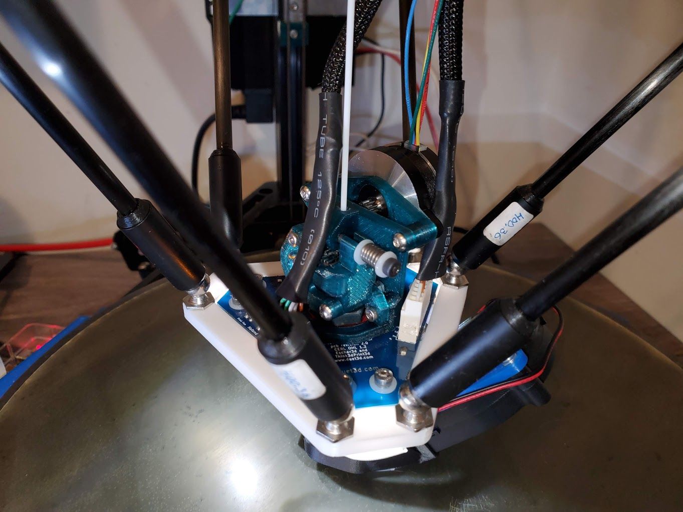
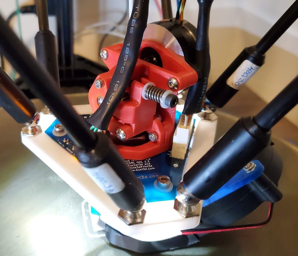
@Hergonoway said in Smart Effector including toolboard-capabilities?:
- why did you choose this ball stud placement? Wouldn't it been easier to "just" offset the ball studs from the smart effector set horizontally to reach the desired clearance?
I've been playing around with the model to see what it might take to get it to fit well on a smart effector. The 64mm spacing that @mrac1 is using does work, but I don't know if that's the "best" solution.
Also, there's more to arm spacing than just the gap between two parallels arms: there's also the gap between the "centers of articulation" (as described here: https://reprap.org/wiki/Delta_geometry#Effector_stability and referenced there as "b".) From that page, there's a theoretical relationship between effector stability, the arm spacing, and "b".
For reference, @dc42's smart effector has an arm spacing of 55mm, and a "b" of 12mm. Using the formula provided on that linked page (Tilt Effector Stability = (Arm space)²/b), the smart effector has a "TES" of ~252.08.
Assuming that theoretical work is accurate (or close to accurate), the effector from mrac1 has a much lower stability of ~134.94. (64^2 / 30.354)
From that, I started playing around in Fusion360 modeling arm spacing, and set thing up so that the "b" value is computed automatically based on the arm spacing in order to maintain a "TES" value of 252.08. (I just force the "b" value to be "( arm space )² / 252.08 mm.") Then I linked mrac1's excellent extruder model on top of the resulting sketch and kept adjusting the arm space until the arms (and arm movement) was completely clear of the lines connecting all 6 ball joints. (My choice of clearance was somewhat arbitrary. Some delta builds would need more space, and others would need less.)
Here's what it looks like with an arm spacing of 74mm. In this case, "b" is 21.72mm.
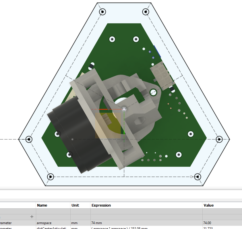
Note that this is pushing it really close. Here's a snippet showing 80mm (with "b" of 25.39):
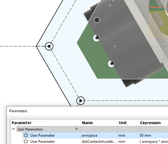
So, at 80mm arm spacing, there's more wiggle room, but on some delta geometries where the print area is actually larger than the triangle formed by the X/Y/Z verticals (and therefore carriages), even this might not be enough. (I think some SeeMeCNC machines are like that.)
I also put the "CR" version of the Orbiter on my sketch to see how that would fit. Specifically, I used the "CR" version of the oribiter. This specific version has a more centered filament path compared to all other available/published versions. (The "v1.5" that's available for sale would stick out an additional ~9mm.) I rotated the model for what I perceived to be the best fit (with 80mm arm spacing):
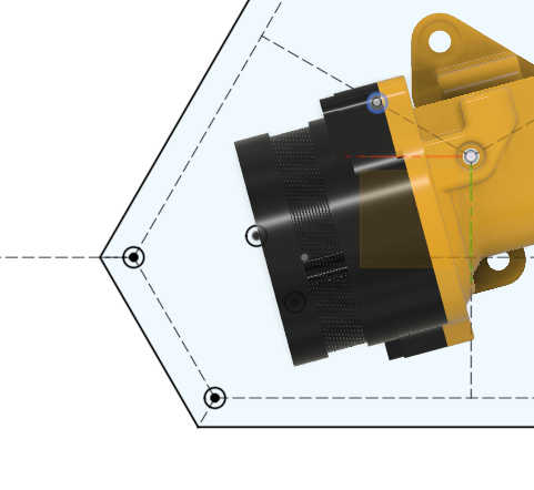
One important difference when comparing the orbiter and mrac1 extruder pictures above is that they are shown with different stepper models (when they actually use the same one.) According to LDO specs, the stepper should have a total thickness of 17.5mm. The model with the mrac1 pictures has a 20mm thick stepper and the orbiter model as a 17.0mm thick stepper.
Another important difference that isn't shown at all in these pictures is the vertical height of the stepper. (Due to delta arms and angles, this is important for determining clearance.) The mrac1 extruder has the stepper centered 39mm above the effector. The orbiter extruder has the stepper is centered 18mm, PLUS the height of any adapter, above the effector. (It might also be possible to modify the orbiter model to not need any adapter.)
Hopefully all this typing and snipping is useful to someone. 
Take care
Gary
 )
)


