Posted this part in the RatRig discord server. But it has a limited Duet3D fan base. So posting here too.
https://www.printables.com/model/967347-eva3-back-plate-tension-less-duet3d-tool-board
Posted this part in the RatRig discord server. But it has a limited Duet3D fan base. So posting here too.
https://www.printables.com/model/967347-eva3-back-plate-tension-less-duet3d-tool-board
@kipk
I have reserved one at
https://www.dold-mechatronik.de/
They expect it to be in stock next week.
@jay_s_uk Great tip, thank you. i will look into that.
Both that wiki and the GCode Dictionary explains thing with the term "Z leadscrews" which is correct in some hardware configurations. But it fooled me, maybe reading too quickly and not fully comprehending tings.
I propose a change to the use of "pivot point" or equivalent to make things a bit less likely to misunderstand.
@droftarts I have limited knowledge in this area, but would it be possible by using an arduino converting it to an analog signal and use that signal as a temp sensor on the Duet?
One would then get a curve plotted in the web interface and a neat way to control an extraction fan with "temp" levels in the M106 command.
Final settings (for future use by anyone interested):
config.g
-----------------------------------------
; Drives
M584 X0:3 Y1:4 Z2 U3 V4 P3; Three axis visible

; Tools
M563 P0 D0

; Drive direction
M569 P0 S1                       ; Drive 0 goes forwards
M569 P1 S1                       ; Drive 1 goes forwards
M569 P2 S1                       ; Drive 2 goes forwards
M569 P3 S1
M569 P4 S1

; Steps and Speed
M92 X80.00 Y80.00 U80.00 V80.00 Z4000.00 ; Set steps per mm
M566 X900.00 Y900.00 U900.00 V900.00 Z12.00; Set maximum instantaneous speed changes (mm/min)
M203 X6000.00 Y6000.00 Z180.00 U6000.00 V6000.00; Set maximum speeds (mm/min)
M201 X500.00 Y500.00 Z20.00 U500.00 V500.00; Set accelerations (mm/s^2)
M906 X800.00 Y800.00 Z800.00 U800.00 V800.00 I30; motor currents (mA) and motor idle factor
M84 S30  ; Set idle timeout

; Axis Limits
M208 X0 Y0 Z0 U0 V0 S1                 ; Set axis minima
M208 X600 Y400 Z100 U600 V600 S0           ; Set axis maxima

; Endstops
M574 X1 Y1 U1 V1 S0               ; Set active low and disabled endstops

homex.g
----------------------------------------
M584 X0 U3 P5; split steppers, 5 axis visible
G91 ; relative moves
G1 X-650 U-650  F450 S1 ; fast homing X and U in parallell
;G92 X0 U0 ; Make adjustments to square axis here
M584 X0:3 P3; join steppers, 3 axis visible
G90dsmudger
I would say these are major steps
Original connectors can be forced into the Duet board, but I ended up making adapters both for the steppers and the hot end. Pictures below show before the adapters during "proof of concept phase". On the hotend it self I made a new board using experimental circuit board and matching connectors. There was too much interference in the ribbon cable for the signal from the IR board so I added an ethernet (twisted pair) cable for that.
If there are any questions I would be happy to help.


Never used them, can not reach them with my fingers when mounted on my printer.
I got no voltage at those points. Not with or without an object within range.
I made several tests to be sure sonce i did net get any readots at all.
As a last test I was thinking of trying to shine some IR light on the sensor using the old ormerod sensor or a tv remote.
Settimg this up it started working again!!?? I did not get to the point using another IR source.
I have disconnected it several times and kept working then it stopped working again.
I have upgraded my duet-controlled Cetud3d with a Hemera extruder. I have been testing how fast it can print and still have not reached its limits.
Peak speed in the PLA print below is about 250 mm/s , reported by DWC.
This is unnecessary and so much FUN 
https://youtu.be/gCN8IdGvwas

@fotomas
Did a test, first layer transparent PLA layed down in a concentric pattern. On top of that black and red PLA and lastlt a black layer. All layers printed with a .4 mm nozzle and layerheight .4 mm. The coaster has a diameter of 80 mm.
There some moiré effects so there are things to improve. But as a first test I think it worked out fine.
(The text translates to "transmission interruption")


I have beed inspecting and inspecting and not seen anything indicating cracks or movement.
That seems to have got it up an running again. I have probably closed a crack somwhere.
If it stops workkng again I may let a friend of mine re-solder all componets with one of those soldering heat guns.
That may invalidate the warranty, I dont know but may be worth a try.
Inthink we can close this thread.
Thank you for all help!
I have designed a smal but effective bracket that supports the Z-axis on the Cetus.
The fit may vary sepending on the version of Cetus and when it was manufactured.
But it is pretty easy to draw one, if it does not fit.
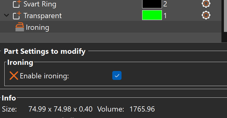
@engikeneer Testing ironing on top of first/bottom layer.... will know more in 1hr...
Did not work. For some reason did not the setting have any effect.

Maybe not intended to be used like that or me doing something wrong....
I want to share may latest project, a detachable Panel Due caring using RJ45 connectors.
I am building a Duet controlled MPCNC and to be able to move my panel due between my printer and the upcoming CNC. I used RJ45 connectors from a server room patch panel.
I have tested with different LAN cable lengths, 3 m works but not 10 m  , it communicated but the touch control did not respond. 3 m will be more than enough.
The hole is for an emergency stop button to be used with the CNC. This is a prototype printed printed with a 0.6 nozzle and 0.4 layer height so it is not the prettiest print.
Happy with the solution so far.


After a print my printer stands pre-heated (at 100C) in standby. When I start slicing my next print I click the heater in DWC to get to active and prepare for printing temp.
But going from standby to active resets all the temps to zero.
I'm a doing something wrong, or is it not ment to be used like this?
Or maybe it is a bug...
Duet Web Control 2.0.0-RC6
After finding and adressing several issues I belive it is working fine now.
I have:
Lowered the jerk value for Z to 15
Let the bed soak properly before do bed mesh (temp 80 )
Replaced lost screw, one of three holding the hotend to the heatsink. This was hidden by the silicon sock on my Phaetus Rapido hotend.
I think the jerk value was the thing but the other two brought a fair amount of inconcistency too.
So i will end this thread/question here. Thank you for all the help and a little extra to Phaedrux.
Since this is a RC2 it is probably not the time asking for new features. But this is more of an adjustment ...
Move the extrusion window a bit lower so the extruder temp can be seen while manually extruding.
@oliof that is exactly what i did, see comment at the top of config.g