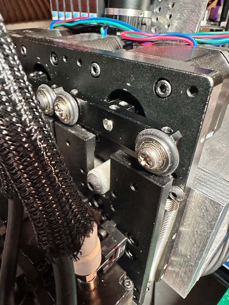
It just Stepper motor which is CAM driven, no belts or no leadscrew
Posts made by developeralgo222
-
RE: Correct steps per mm for Z axis to move 1mmposted in General Discussion
-
Correct steps per mm for Z axis to move 1mmposted in General Discussion
Any Quick suggestions:
On my PnP Machine, i have 3 x NEMA 17 steppers Motors BD4248 with 1.8 deg./step , 200 KHz used for 3 x Z-axes type ( Z, U, V) on Duet 3HC using Duet Internal (In-built) Drivers
-
5mm (0.2") Diameter Drive Shaft . i.e The circumference = 1 complete revolution (360 degrees) = 15.71 mm
-
360/1.8 = 200 steps/revolution
-
So steps/mm on Z-axes = 200/15.71 steps/mm = 12.73 steps/mm
i think i might be calculating it wrong ???
My goal is to have OpenPnP synchronized with Duet3 Controller board so an OpenPnP command for Z axis to move 1mm actually moves 1mm on the Z-axis on the machine
My Current Z-axes configs on Duet3 Controller that need adjustment
M584 Z1.0 U1.1 V1.2  R0 S0      ; LIN R0 = LINEAR ,  R1 = ROTATION
M350 Z32 U32 V32 I1           ; configure microstepping with interpolation
M92 Z32 U32 V32               ; set steps per mm
M566 Z900.00 U900.00 V900.00  ; set maximum instantaneous speed changes (mm/min)
M203 Z60.00  U60.00  V60.00   ; set maximum speeds (mm/min)
M201 Z60.00  U60.00  V60.00   ; set accelerations (mm/s^2)
M906 X800 Y800 Z800        ; set motor currents (mA) and motor idle factor in per cent
M84 S30                       ; Set idle timeout
My OpenPnP Configs
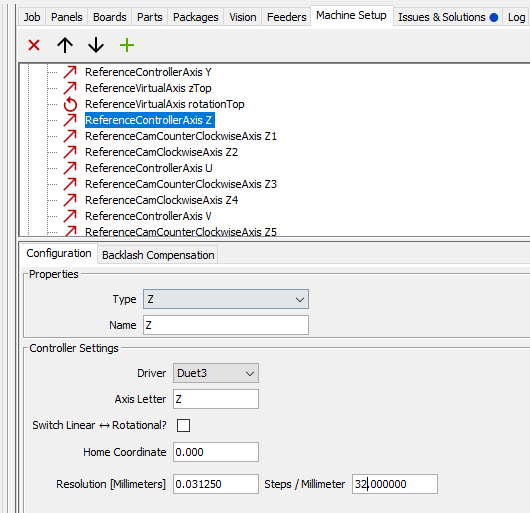
Any help or pointers ?
-
-
RE: Reading Sensor Pressure from Analog outputposted in General Discussion
@infiniteloop Thanks guys for the help i will test it this weekend
-
RE: Reading Sensor Pressure from Analog outputposted in General Discussion
currently i only have
M308 S1 P"2.io0.in" Y"linear-analog" A"VG1" F0 B0.0 C-101 V0.0 U0.0i am not using U & V as @dc42 mentioned above.
If i understand what you explained above would this work for the subset range
i will test it but would this work as my start of testing
M308 S1 P"2.io0.in" Y"linear-analog" A"VG1" F0 B22 C-123 V0.0 U0.0OR
M308 S1 P"2.io0.in" Y"linear-analog" A"VG1" F0 B22 C-101 V0.0 U0.0and also do i need to include U & V values in the M308 command if both the values are at 0.0 ? or i can leave them out and just use B & C values like this and no worry about including U & V on the command
M308 S1 P"2.io0.in" Y"linear-analog" A"VG1" F0 B22 C-123 -
RE: Reading Sensor Pressure from Analog outputposted in General Discussion
Managed to mount 12 resistors ( that i had in hand creating 6 Voltage Dividers ( 1.8K & 3.3K ) per connection and it seems to work read the values fine now . Now my issue is how to Calibrate it correctly .
Sensor Analog ( 1 ~ 5V) ===> Duet Analog ( 0 ~ 3V getting a Max of 3.24V) . Ideally probably i need to use 1.7K resistor so at get 3.3V or 1.6K resistor(assuming leakage or noise) to get 3.33V
@ 0 kPa on the Sensor ===> Duet reads -22 kPa
@ 40 kPa on Sensor ===> Duet reads -38 kPa
@ 55 kPa on Sensor ==> Duet reads -53 kPa
@ 65 kPa on Sensor ==> Duet reads -63 kPa
and so on
Not sure how to calibrate it correctly using U & V values for adjusted reading
-
RE: Reading Sensor Pressure from Analog outputposted in General Discussion
i can't seem to get a good voltage divider to purchase that can handle 6 outlets. Do you have any link of any voltage divider that can do that and is being sold anywhere ? i don't have time to design one at the moment
-
RE: Reading Sensor Pressure from Analog outputposted in General Discussion
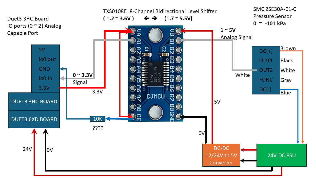
@gloomyandy , ok will do that. Quick question, Do i need to connect a 10K resistor between the 3.3V converter source i.e Tie VA(3.3V) to OE then to 10K resistor to GND as per the TXS0108E Datasheet ?
-
RE: Reading Sensor Pressure from Analog outputposted in General Discussion
@gloomyandy Yes i did before i plugged everything in . 5V on the High side and 3.3V on the low side. Let me just do it again to see if that changed with the load
-
RE: Reading Sensor Pressure from Analog outputposted in General Discussion
@gloomyandy , Voltage divider is simple and works most of the time (Dividers tend to be unreliable sometimes when you need accuracy ) but i have 6 sensors that are connected and are being used as Vacuum Pressure Sensing Actuators for my Pick-and-Place machine . i need high accuracy and robust reliability , that's why i used a Voltage Level Shifter
-
RE: Reading Sensor Pressure from Analog outputposted in General Discussion
@droftarts
Thanks Ian, i have tried connecting directly & through a level Shifter and none seems to work correctly .I am sure i am not the only one who has dealt or is dealing with this issue on Duet3 boards.
How to correctly read Pressure Sensor values either using a Digital NPN output signal ( 1 =True , 0=False) or Analog Voltage/Current Signal output ( Variable range ). i have made the connections and double checked everything but can't get it to work on Duet3 Boards but it works great on my Arduino and other boards no issues at all.
-
RE: Reading Sensor Pressure from Analog outputposted in General Discussion
@gloomyandy . Any suggestion of a solution if a Logic level shifter is not the right solution ?
AFAIK, these are the recommended solutions to solve this issue. Are you suggesting anything different from this?
-
Voltage Divider ( simple but not robust)
-
Bi-directional Logic Level Shifter ( Robust )
-
Zener Diode Clamp
-
Opto-isolator
-
-
RE: Reading Sensor Pressure from Analog outputposted in General Discussion
i have 6 ports connected to 6 sensors as indicated above ( Board 2 (3HC) = 2.io0.in , 2.io1.in , 2.io2.in & Board 3 (3HC) = 3.io0.in , 3.io1.in , 3.io2.in ) and they are all behaving the same way.
i have tried on the 6XD analog capable ports and they are behaving the same way too
-
RE: Reading Sensor Pressure from Analog outputposted in General Discussion
As per my testing i don't think Analog port on Duet3 3HC seems to be working correctly. It seems that as per the Analog connection , i should be getting varied Analog pressure reading from the Sensor but it looks like its behaving as if it only triggers to a Max Value set when the Set pressure is met or it remains at the Minimum set Value so long as the Set pressure on the sensor is not yet met. Its behaving more like a NPN output instead or analog output .
E.g i have this on Duet3
M308 S1 P"2.io0.in" Y"linear-analog" A"VG1" F0 B0.0 C-101 V0.0 U13.5and on SMC Pressure Sensor i have set it to - 40 kPa for testing
When the
-
Sensor reads/displays 0.0 ~ -39.9 kPa =====> Duet reads -0.1 ~ 0.1
-
Sensor reads/displays -40.0 ~ -101 kPa =====> Duet reads -87.5 ~ -87.9
it seems to be behaving like a digital NPN output yet its analog output
-
-
RE: Reading Sensor Pressure from Analog outputposted in General Discussion
at 0.0 kPa those above values work but they extremely skewed as you start to have pressure reading. i am not sure what are the correct values to have it working .
e.g Actual Sensor Display = 0.0 Kpa , Duet Adjusted Reading = 0.0 kPa But
Actual Sensor Display =70.0 kPa , Duet Adjusted Reading = 86.8 kPai then let it run and kept reading the observing the values compared to what is being read. The Duet readings don't change that much while the actual pressure is decreasing. I am not sure if Adjusted reading formula actually works with Pressure sensor readings
in a simple way of y = ax+b ==> a = slope & b = offset , y = Voltage (1 ~ 5V ) and X = Pressure ( 0 ~ -101.0 kPa )
i.e y = 0.043x + 0.6 ===> x = (y/0.043 ) - (0.6/0.043) ==> x = 23.25y - 13.90
- Looking the formula AdjustedReading = (RawReading * (1.0 + V)) + U
But if i equate 1.0+V = 23.25 ==> V = 22.25 & U = -13.90
i get an error that V is "Too High".
What are the ranges of V & U ?
-
Reading Sensor Pressure from Analog outputposted in General Discussion
I have SMC ZSE30A-01-C Pressure Sensors with 1 NPN output (Black) + Analog voltage output (white wire) and have configured them with M308 Commands, and also according to the datasheet ZSE30A_ISE30.pdf
M308 S1  P"2.io0.in" Y"linear-analog"  A"VG1"  F0  B0.0  C-101
M308 S1  P"2.io1.in" Y"linear-analog"  A"VG2"  F0  B0.0  C-101
M308 S1  P"2.io2.in" Y"linear-analog"  A"VG3"  F0  B0.0  C-101
M308 S1  P"3.io0.in" Y"linear-analog"  A"VG4"  F0  B0.0  C-101
M308 S1  P"3.io1.in" Y"linear-analog"  A"VG5"  F0  B0.0  C-101
M308 S1  P"3.io2.in" Y"linear-analog"  A"VG6"  F0  B0.0  C-101
More info:
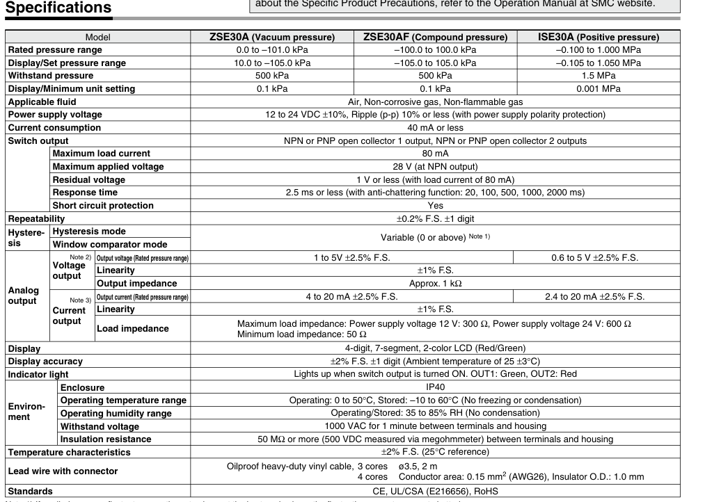 .
.
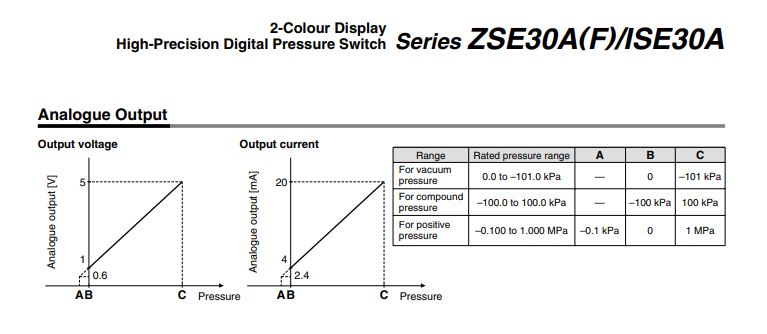
I am able to read the values but they are wrong . Are offset by almost -38 , Actual Value = 0.0 while the reading returns -38 or -37.x as the value
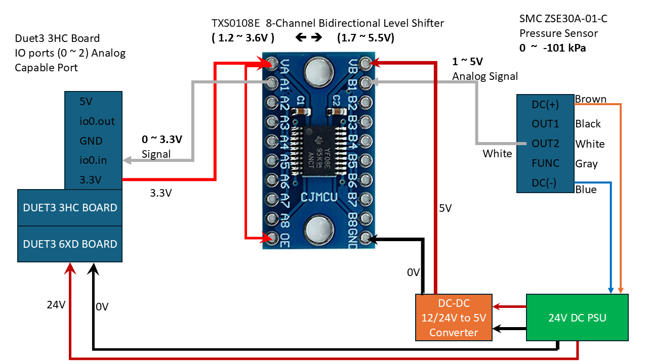
Duet3 Analog ports on 3HC (0 to 3.3V signal) ====> isolated 8-Port channel Bidirectional Level Shifter 3.3V to/from 5V ==> SMC ZSE30A-01-C Analog port ( 1 - 5V signal).
How do i configure this correctly ?
i was also looking at an Old Arduino code to see if i can get some help from that :
SMC vacuum sensor  ZSE30A-01-C-L
===============================================
ARDUINO CODE
===============================================

// 1 Volt is an ADC value of ~205 with a 10-bit ADC and 5V Aref

const int offset = 205;  // calibrate zero pressure

Kpa = (analogRead(A0) - offset) * 101 / (1023 - offset);
I have managed to fiddle a round and get to this to try solve my issue but i am not sure if this is the correct way to configure it.
M308 S1  P"2.io0.in" Y"linear-analog"  A"VG1"  F0  B0.0  C-101  V0.00 U13.5
M308 S1  P"2.io1.in" Y"linear-analog"  A"VG2"  F0  B0.0  C-101  V0.00 U13.5
M308 S1  P"2.io2.in" Y"linear-analog"  A"VG3"  F0  B0.0  C-101  V0.00 U13.5
M308 S1  P"3.io0.in" Y"linear-analog"  A"VG4"  F0  B0.0  C-101  V0.00 U13.5
M308 S1  P"3.io1.in" Y"linear-analog"  A"VG5"  F0  B0.0  C-101  V0.00 U13.5
M308 S1  P"3.io2.in" Y"linear-analog"  A"VG6"  F0  B0.0  C-101  V0.00 U13.5
i got adjusted values at 0.0 kPa that now fall within expected readings (-0.1 - 0.1 ) kPa but i still need to test with actual air pressure running through to see what the values are going to be and if they conform to the Adjusted Reading e.g is Actual -50.0 kPa pressure reading on the sensor going to be read as -50.0 (+/- 0.2) kPa with the adjusted reading or it will skew or extremely deviate from the actual sensor displayed values.
11/14/2024 , 12:24:15 PM       M308  S1
                               Sensor 1 (VG1 Pressure) type Linear analog using pin 2.io0.in, last error ok, offset adjustment 13.5, slope adjustment 0.000, adjusted reading -0.1, unfiltered, range 0.0 to -101.0
Here is brief snapshot of my connections :
-
RE: Correct way to set Steps Per mm for X and Yposted in General Discussion
Thanks for your help. Here is what i have adjusted them to
M569 P0.0 S0 T2.5:2.5:2.5:2.5           ;  2.5us timings between pulses for X-axis
M569 P0.1 S0 T2.5:2.5:2.5:2.5           ;  2.5us timings between pulses for Y-axis
.
.
.
M350 Z16 U16 V16 W16 A16 B16 C16 D16 'G16 I1         ; configure microstepping with interpolation.
M92 X100.00 Y100.00 Z80.00 U80.00 V80.00 W8.888 A8.888 B8.888 C8.888 D8.888 'G8.888     ; set steps per mm . Ballscrew Pitch = 10mm/rev.
M566 X900.0 Y900.0 Z900.0 U900.0 V900.0 W900.0 A900.0 B900.0 C900.0 D900.0 'G900.0  P1     ; set maximum instantaneous speed changes (mm/min) and use Jerk policy 1
M203 X51000 Y51000 Z6000 U6000 V6000 W3600000.00 A3600000.00 B3600000.00 C3600000.00 D3600000.00 'G3600000.00    ; set maximum speeds/feedrate (mm/min)
M201 X5000.00 Y5000.00 Z2000.00 U2000.00 V2000.00 W180000.00 A180000.00 B180000.00 C180000.00 D180000.00 'G180000.00     ; set accelerations (mm/s^2)
M906 Z1360.0 U1360.0 V1360.0 W560.0 A560.0 B560.0  C560.0 D560.0 'G560.0  I100        ; set motor currents (mA) and motor idle factor in per cent
As concerns Jerk , Duet measurement are in mm/min but openPnP are in mm/s^3
in order to convert that into mm/s^3 for OpenPnP do i just need to take Duet's config value and multiply by (60 * 1/S^3 )
i.e 900 mm/min = 900 x 60 mm/s =54000 mm/s x (1/s^2) = 54000 mm/s^3
is this correct assumption ? or Both Duet & OpenPnP must have be synchronized by having same Value ?
From this config is there anything you think might be a little out of place i.e Too high or too low
-
RE: Correct way to set Steps Per mm for X and Yposted in General Discussion
@droftarts
I think you clearly explained it to me . i was struggling to understand the link & calculations as to why if i sent a command of 100mm and i have HSS86 Driver with 10000 pulses/rev and M92 X100 Y100 configured . what was going on .That's clearly explained now i see why i was getting all confused about the command and the steps/mm calculations
Thanks so much for explaining that clearly
-
RE: Correct way to set Steps Per mm for X and Yposted in General Discussion
Can you confirm . I just tested with Duet DWC Console ( Not involving OpenPnP at all)
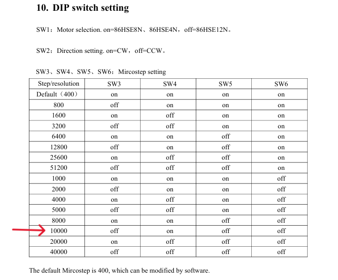
HSS86 Driver is set to 10000 pulses/rev == (10000 pulses/rev ) / 10 mm/rev = **Maximum Possible/allowed of 1000 pulses/mm at 10000 pulses/rev HSS86 Driver setting **
Test 1: M92 X1000 Y1000 get 1:1 relation with Max Speed = 200 mm/s == 12000 mm/min before stall/skip
G1 H2 X100 F12000Test 2: M92 X100 Y100 get 10:1 relation with Max Speed = 2000 mm/s == 120000 mm/min before stall/skip
G1 H2 X100 F120000This seems to indicate that the HSS86 Driver set value using DIP Switch to 10000 pulses/rev == 1000 pulses/mm is simply maximum reference value allowed at that setting as per the Ballscrew Pitch.
So if you configure something like M92 X50 Y50, i.e 50 steps/mm on Duet then Duet will send that along to the driver and since the driver is expecting 10000 pulses/rev == 1000 pulses/mm, it takes that (1000 pulses(steps)/mm ) / 50 steps/mm = 20 . i.e every measurement on Duet in relation to X & Y axis motor movements will be in 20:1 ratio as per this example where 200mm on Duet will move 10 mm on actual Machine
G1 H2 X200 F100000At first i thought it was Duet /OpenPnP but i just realized its not. The ratio occurs depending on what Duet/OpenPnP send to the HSS86 external driver and the HSS86 Driver calculates the measurement ratio for moving the motor
Since i am able to configure a lower value of M92 X100 Y100 and it works fine and sends that lower steps/mm value from Duet DWC to the driver towards the motor creating 10:1 ratio measurement.
This test outcome is a surprise to me.
-
RE: Correct way to set Steps Per mm for X and Yposted in General Discussion
@droftarts
Fantastic thanks for that clarification. So from your explanation it implies that the Higher "steps/mm" number on Duet M92 Xnnn Ynnn ===> The Lower the speed /Feedrate (Limited Speed) ? -
RE: Correct way to set Steps Per mm for X and Yposted in General Discussion
Do you mean setting steps /mm on Duet to 1000 steps/mm ? i.e
M92 X1000 Y1000 ? as you said it will limit the speed. i think my problem is that it seems 100 steps/mm ( 1000 pulses/rev) is fine . But when i enter that value on the X & Y axis on the OpenPnP side its on 10:1 ratio . That is 10mm move on the OpenPnP software /Duet DWC console actually moves machine X & Y 1 mm physically i.e 10:1 ratio. That creates a few issues with OpenPnP configuration , it assumes 1:1 relation in steps/mm that is configured on Duet3 as it uses it for other movements like backlash calculations etc