Damn it. Apparently selected wrong Duet3D firmware. I'm connected.
Thanks for the help and sorry for wasting your time.
Have a good weekend and stay healthy.
-Peter
Damn it. Apparently selected wrong Duet3D firmware. I'm connected.
Thanks for the help and sorry for wasting your time.
Have a good weekend and stay healthy.
-Peter
@sebkritikel: yeah changing the X to U made all the difference . D'oh! seems stupidly obvious now.
@o_lampe: Made the changes and added the second tool screen grab below.
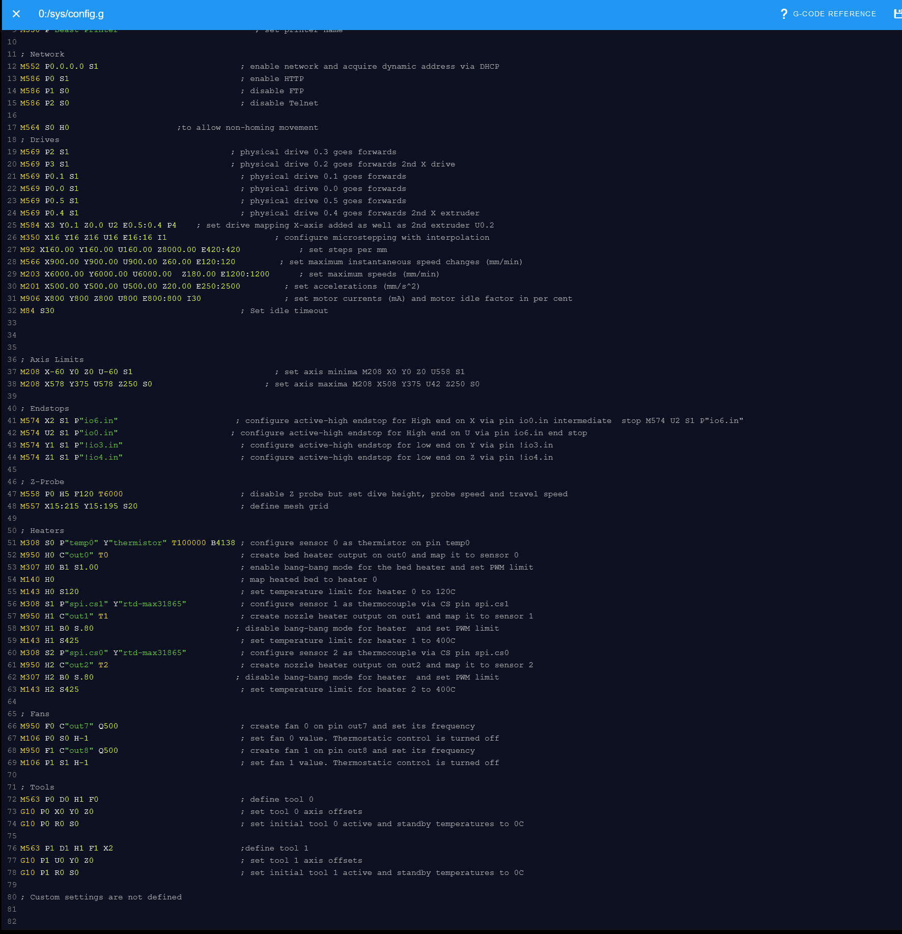
All is working as I expect, on to the next steps of my custom testing.
Again thanks for the time to look at my code.
-Peter
@fcwilt Right and understand what you are saying.
I built my sensors and mounts, so obviously, was following the wires closely. I ended up using ribbon cable that I had, so there's no color code, just notes stating what they are.
I would have done the same thing that you did otherwise.
@sebkritikel: yeah changing the X to U made all the difference . D'oh! seems stupidly obvious now.
@o_lampe: Made the changes and added the second tool screen grab below.

All is working as I expect, on to the next steps of my custom testing.
Again thanks for the time to look at my code.
-Peter
Thanks Sebritikel and o_lampe,
Yeah the files were created by the configurator and I tried various modifications using https://duet3d.dozuki.com/Wiki/ConfiguringMultipleIndependentXcarriagesCartesian#Section_Calibration
as well posts found on the 'nets.
Later today I'll try the changes you say are needed o_lampe and any that you offer Sebritikel and report back when I do.
If you find anything else to try or have any other suggestions feel free to pass along.
Have a good day/night.
-Peter
Yeah getting this to work has been a learning experience. Made a bit of headway when I included the P4 in the M584 line. But clearly missing something else.
Thanks for responding.
-Peter
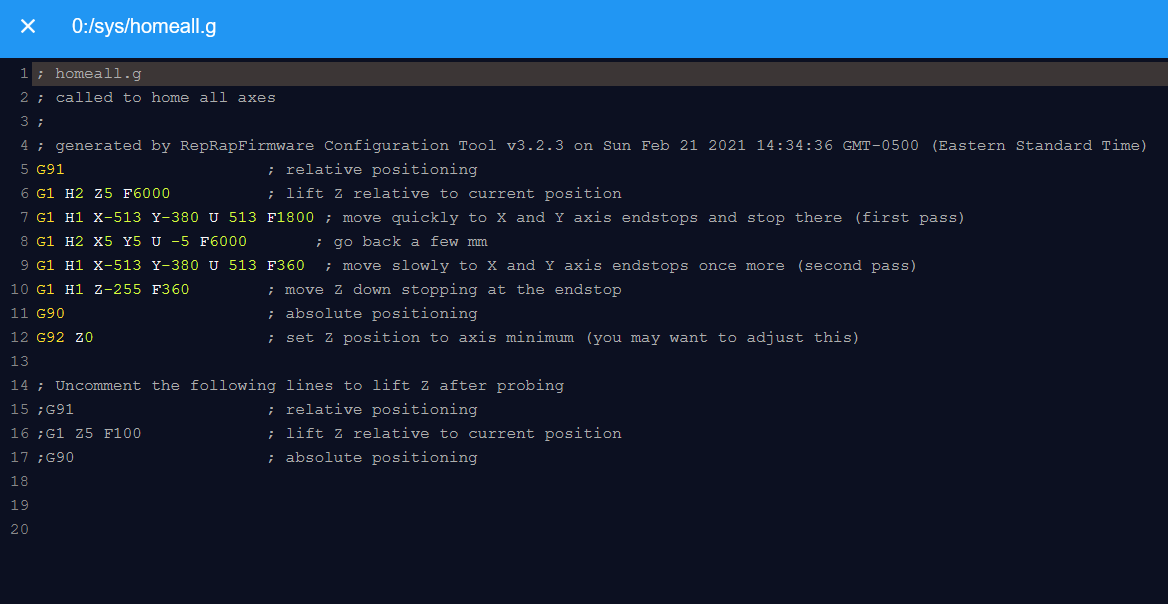
Here are screen grabs:
Config.sys
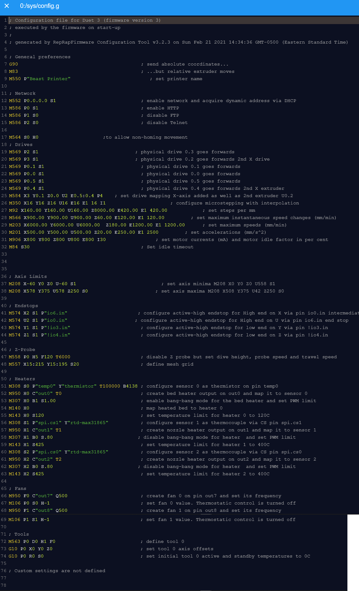
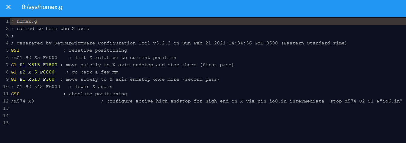
and Homing. Though never used HomeAll.
HomeX:
HomeU:
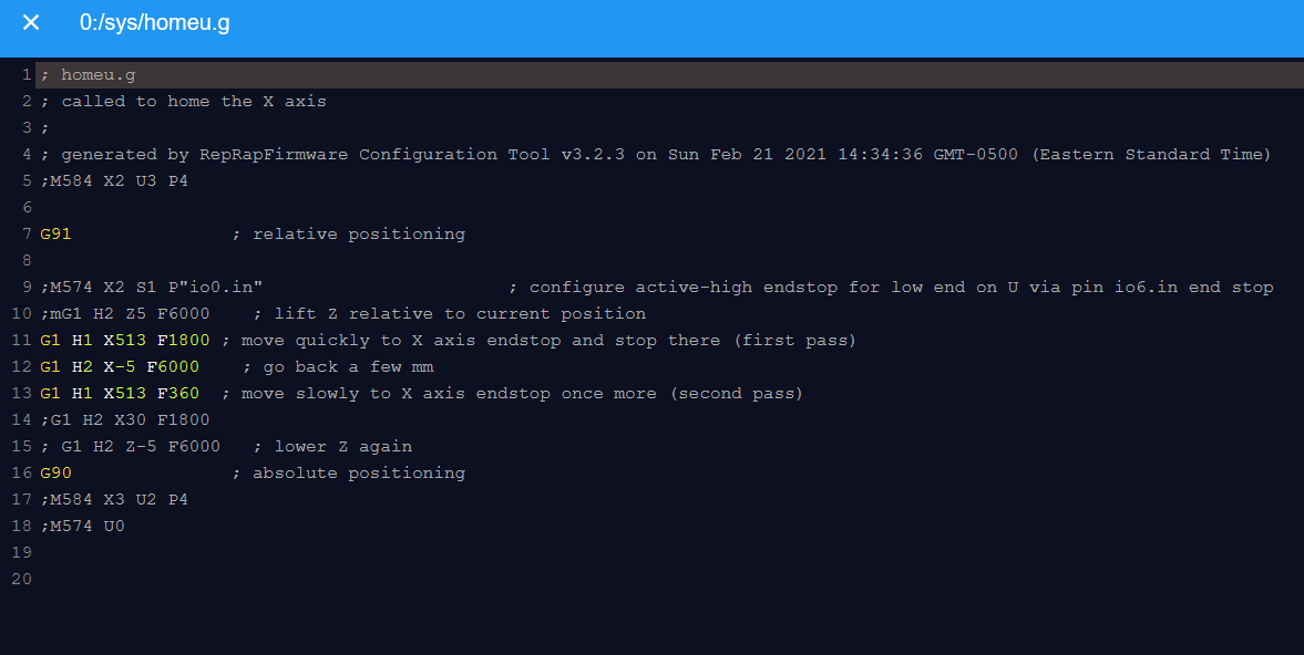
HomeAll:
Hello,
Hope all are doing well these days.
More on the subject line:
Using M564, I can move both the X and U carriages independently via command line or using pre-sets, as expected.
When tiring to homing either one, which one first doesn't matter, the X carriage only moves in both cases.
When X is homed:
-it pushes the U carriage.
-for all intents and purposes homes on the X designated endstop.
-X tool position is updated
When U is homed:
-X carriage pushes the U-carriage.
_Homes on the X-endstop.
-I get an "G28 U Error: homing failed" message.
-X Tool position is updated.
Post either homing, X and U carriages will move independently, via command line or using pre-sets.
Flipping the X and U motor mapping in config.sys', the above happens minus X pushing U carriage as they are 'flipped'.
Endstop wise, X-endstop is the furthest on the right, and U-endstop (E0 wired) about an 1" to the left of the X-endstop. I want both to home on the right side of the axis.
Code
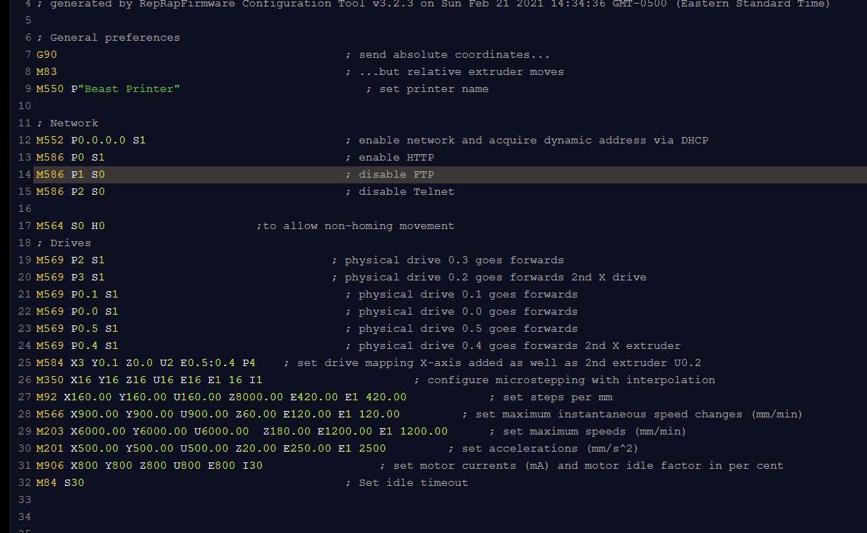
Config.sys - partial:
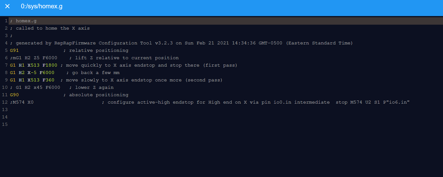
Both X and U homing are the same:
Thanks
-Peter
@o_lampe Thank you for responding. I'll take a look into what you have posted.
My machine is fundamentally a Cartesian 3D printer, when I say custom, it's that I have designed and fabricated custom mechanical parts of it.
I have been trying to follow this https://duet3d.dozuki.com/Wiki/ConfiguringMultipleIndependentXcarriagesCartesian#Section_Creating_new_axes
From preliminary looking into your post and seeing if there's is any relation to the link above, I did see that I missed a line about how endstops and 'extra' axis are linked - so to speak. I was starting to wonder about this based on what I was seeing in my tests. Ah maybe need to add some custom wiring....
The challenge continues, thanks again for your input (it's interesting in of itself).
-Peter
Hello,
Hope all are well.
Build: Duet3D, using DWC
For physical orientation.
MY custom printer: IDEX. On the same physical axis:
-Left side extruder = X-axis.
-Right side = U-axis.
Issue:
When I 1st Home U, it physically works, U-extruder moves as I want, but I get a "G28 U Homing failed", I see that the X-axis coordinates are updated, not U, and the Home X button is blue - not Home U.
If I continue, ignoring the Homing Error, and I push the "Home X" or "Home U" button, the U-extruder will move (again) in both cases crashing as there's no more travel.
If I 1st Home X, the U-extruder will move, running the HomeX routine - no Homing Error and the X-position is updated. If I then run the "Home U" routine the the U-extruder runs (again) the Home U routine, but I get the G28 error and the X-position is changed.
From playing around with, drive mapping in config file I can control either extruder, so they are 'independently' operational.
I'm using trying to use the same limit switch for both, printer is physically set up to allow it.
I have played around with the both HomeX and U files (Motor & endstop mapping) but no improvement, sometimes making it worse. Some remnants of which is in the code(s) below.
Thank you for any help.
-Peter
Relevant code?
Config:
; Drives
M569 P0.3 S1 ; physical drive 0.3 goes forwards
M569 P0.2 S1 ; physical drive 0.2 goes forwards 2nd X drive - U-extruder
M569 P0.1 S1 ; physical drive 0.1 goes forwards
M569 P0.0 S1 ; physical drive 0.0 goes forwards
M569 P0.5 S1 ; physical drive 0.5 goes forwards
M569 P0.4 S1 ; physical drive 0.4 goes forwards 2nd X extruder
M584 X0.2 Y0.1 Z0.0 U0.3 E0.5:0.4 ; set drive mapping X-axis added as well as 2nd extruder U0.2
M350 X16 Y16 Z16 U16 E16 E1 16 I1 ; configure microstepping with interpolation
M92 X160.00 Y160.00 U160.00 Z8000.00 E420.00 E1 420.00 ; set steps per mm
M566 X900.00 Y900.00 U900.00 Z60.00 E120.00 E1 120.00 ; set maximum instantaneous speed changes (mm/min)
M203 X6000.00 Y6000.00 U6000.00 Z180.00 E1200.00 E1 1200.00 ; set maximum speeds (mm/min)
M201 X500.00 Y500.00 U500.00 Z20.00 E250.00 E1 2500 ; set accelerations (mm/s^2)
M906 X800 Y800 Z800 E800 I30 ; set motor currents (mA) and motor idle factor in per cent
M84 S30 ; Set idle timeout
; Axis Limits
M208 X0 Y0 Z0 U0 S1 ; set axis minima M208 X0 Y0 Z0 U558 S1
M208 X508 Y375 U508 Z250 S0 ; set axis maxima M208 X508 Y375 U42 Z250 S0
; Endstops
M574 U2 S1 P"io6.in" ; configure active-high endstop for High end on X via pin io0.in intermediate stop
M574 X2 S1 P"io0.in" ; configure active-high endstop for High end on U via pin io6.in end stop
M574 Y1 S1 P"!io3.in" ; configure active-high endstop for low end on Y via pin !io3.in
M574 Z1 S1 P"!io4.in"
HomeU:
; homeu.g
; called to home the X axis
;
; generated by RepRapFirmware Configuration Tool v3.2.3 on Sun Feb 21 2021 14:34:36 GMT-0500 (Eastern Standard Time)
G91 ; relative positioning
;M574 X2 S1 P"io0.in" ; configure active-high endstop for low end on U via pin io6.in end stop
;mG1 H2 Z5 F6000 ; lift Z relative to current position
G1 H1 X513 F1800 ; move quickly to X axis endstop and stop there (first pass)
G1 H2 X-5 F6000 ; go back a few mm
G1 H1 X513 F360 ; move slowly to X axis endstop once more (second pass)
G1 H2 X25 F1800
; G1 H2 Z-5 F6000 ; lower Z again
G90 ; absolute positioning
;M584 X0.2 Y0.1 Z0.0 U0.3 E0.5:0.4 P3
HomeX:
; homex.g
; called to home the X axis
;
M574 U2 S1 P"io6.in" ; configure active-high endstop for low end on X via pin io0.in intermediate stop
M574 X2 S1 P"io0.in"
; generated by RepRapFirmware Configuration Tool v3.2.3 on Sun Feb 21 2021 14:34:36 GMT-0500 (Eastern Standard Time)
G91 ; relative positioning
;mG1 H2 Z5 F6000 ; lift Z relative to current position
G1 H1 X513 F1800 ; move quickly to X axis endstop and stop there (first pass)
G1 H2 X-5 F6000 ; go back a few mm
G1 H1 X513 F360 ; move slowly to X axis endstop once more (second pass)
; G1 H2 Z-5 F6000 ; lower Z again
G90 ; absolute positioning
@fcwilt Right and understand what you are saying.
I built my sensors and mounts, so obviously, was following the wires closely. I ended up using ribbon cable that I had, so there's no color code, just notes stating what they are.
I would have done the same thing that you did otherwise.
@Veti Ok. it's a simple mechanical snap switch and appeared to work fine when m119 queried, manual operated and 'multi-meter-ed'.
I'm using this sensor:
https://sensing.honeywell.com/honeywell-sensing-omnipolar-digital-hall-effect-sensor-ic-datasheet-ss351at_ss451a_ss551at_005917-4-en.pdf
Wiring to 3.3V, Gnd and ioX_in pins at the io port, via the upper left wiring diagram in "Figure 4. Wiring Diagrams" section of the PDF. I omitted the pull up resistor as in a few places, it's mentioned that there's one built in to the io port on the Duet. The sensor sinks the voltage, so ioX_in.
@fcwilt I agree 100%.
Granted none of them with a Duet board, but I have designed many electro-mechnical systems at work, that have a mix of sensors (inputs) and never a problem. This is the reason it's a mystery to me.
When it was hall-effect/snap sensors, they all worked 'independently' as described above. When I replaced to the final hall-effect, all I changed/flipped around, was which wires from the sensor went to Vcc, Gnd and io_in, but in the end, same pins being used at the same IO port.
At this point I'll continue my build and if something occurs to me to why, that I can test, I will and report back.