@Dad003 said in My Second build (in progress):
but the tubing couldn't make the bend
Eventually, a spring over the tube helps against kinking?
But this works only, when the tube isn't to stiff.
@Dad003 said in My Second build (in progress):
but the tubing couldn't make the bend
Eventually, a spring over the tube helps against kinking?
But this works only, when the tube isn't to stiff.
@axiom That's the same like extrusion factor in DWC...
@GeneRisi Can you give me a usecase for this wish?
I'm not sure if this is necessary? If you never use a "set" command in your meta code, the global will stay as it is....
@mikeabuilder it's probably better to check if it is > 0 (or eventually not = "null")
then, a single reading should be enough
Hi all
If i'd like to check with meta commends if a print is running, which is the best OM value for that?
I think, there are different possible ways...
Thanks in advance
@jay_s_uk Ok. Thanks.
I refered to the drives defined with M569...
@jay_s_uk Thanks for the info.
I have wired the motion sensors to endstop connectors of the Duet2 board. Additionally i've wired the presence switch to gpin ports of the duex board.
Are the drive numbers defined with the M591 command limitted?
After running config, the following warning appears:
Error in start-up file macro line 139: in file macro line 139: M591: parameter 'D' too high
It's a e3d motion system/toolchanger with Duet2+Duex5, running RRF3.5.3
config.g
; Configuration file for Duet WiFi / Ethernet running RRF3 on E3D Tool Changer
; executed by the firmware on start-up
;
; General preferences
G21                                                          ; Work in millimetres
G90                                                          ; Send absolute coordinates...
M83                                                          ; ...but relative extruder moves
M550 P"Toolchanger"                                          ; set printer name
M669 K1                                                      ; Select CoreXY mode

; Network
M552 P192.168.0.44 S1                                        ; enable network and set static ip
M553 P255.255.255.0                                          ; set network mask
M554 P192.168.0.1                                            ; gateaway
M586 P0 S1                                                   ; enable HTTP
M586 P1 S0                                                   ; disable FTP
M586 P2 S1                                                   ; enable Telnet for connection with RepetierServer

; Drive direction
M569 P0 S0                                                   ; Drive 0 X
M569 P1 S0                                                   ; Drive 1 Y
M569 P2 S1                                                   ; Drive 2 Z
M569 P3 S0                                                   ; Drive 3 E0
M569 P4 S0                                                   ; Drive 4 E1
M569 P5 S0                                                   ; Drive 5 E2
M569 P6 S0                                                   ; Drive 6 E3
M569 P7 S0                                                   ; Drive 7 COUPLER
;M569 P8 S0                                                   ; Drive 8 UNUSED
;M569 P9 S0                                                   ; Drive 9 UNUSED

M584 X0 Y1 Z2 C7 E3:4:5:6                                    ; Apply custom drive mapping
M208 X-35:328.5 Y-49:243 Z0:300 C-45:360                     ; Set axis maxima & minima
M92 X100 Y100 Z800 C91.022 E388:388:388:388                  ; Set steps per mm assuming x16 microstepping
M350 E16:16:16:16 I1                                         ; Configure microstepping with interpolation
M350 C16 I10                                                 ; Configure microstepping without interpolation
M350 X16 Y16 Z16 I1                                          ; Configure microstepping with interpolation
;M566 X400 Y400 Z8 C2 E2:2:2:2							; Set maximum instantaneous speed changes (mm/min)
M566 X200 Y200 Z8 C2 E200:200:200:200                        ; Set maximum instantaneous speed changes (mm/min)
M203 X10000 Y10000 Z1200 C10000 E5000:5000:5000:5000         ; Set maximum speeds (mm/min)
;M201 X6000 Y6000 Z400 C500 E2500:2500:2500:2500		; Set accelerations (mm/s^2)
M201 X3000 Y3000 Z400 C500 E2500:2500:2500:2500              ; Set accelerations (mm/s^2)
M906 X1800 Y1800 Z1330 I30                                   ; Idle motion motors to 30%
M906 E1000:1000:1000:1000 C500 I10                           ; Idle extruder motors to 10%

; Endstops
M574 X1 Y1 S3                                                ; Set X / Y endstop stall detection
M574 C0 Z0                                                   ; C Z endstop

; Z probe
M558 P8 C"zstop" H3 F360 I0 T20000                           ; Set Z probe type to switch, the axes for which it is used and the dive height + speeds
G31 P200 X0 Y0 Z0                                            ; Set Z probe trigger value, offset and trigger height
M557 X10:290 Y20:180 S40                                     ; Define mesh grid

;Stall Detection
M915 X Y S3 F0 H400 R0                                       ; X / Y Axes

; Heaters
M308 S0 P"bedtemp" Y"thermistor" A"Bed" T100000 B4138 C0     ; Set thermistor
M950 H0 C"bedheat" T0                                        ; Bed heater
M143 H0 S225                                                 ; Set temperature limit for heater 0 to 225C
M140 H0                                                      ; Bed heater is heater 0

M308 S1 P"e0temp" Y"thermistor" A"T0" T100000 B4725 C7.06e-8 ; Set thermistor
M950 H1 C"e0heat" T1                                         ; Extruder 0 heater
M143 H1 S305                                                 ; Set temperature limit for heater 1 to 300C

M308 S2 P"e1temp" Y"thermistor" A"T1" T100000 B4725 C7.06e-8 ; Set thermistor
M950 H2 C"e1heat" T2                                         ; Extruder 0 heater
M143 H2 S305                                                 ; Set temperature limit for heater 2 to 300C

M308 S3 P"e2temp" Y"thermistor" A"T2" T100000 B4725 C7.06e-8 ; Set thermistor
M950 H3 C"duex.e2heat" T3                                    ; Extruder 0 heater
M143 H3 S305                                                 ; Set temperature limit for heater 3 to 300C

M308 S4 P"e3temp" Y"thermistor" A"T3" T100000 B4725 C7.06e-8 ; Set thermistor
M950 H4 C"duex.e3heat" T4                                    ; Extruder 0 heater
M143 H4 S305                                                 ; Set temperature limit for heater 4 to 300C


; Tools
M563 P0 S"T0" D0 H1 F2                                       ; Define tool 0
G10 P0 X0 Y0 Z0                                              ; Reset tool 0 axis offsets
G10 P0 R0 S0                                                 ; Reset initial tool 0 active and standby temperatures to 0C

M563 P1 S"T1" D1 H2 F4                                       ; Define tool 1
G10 P1 X0 Y0 Z0                                              ; Reset tool 1 axis offsets
G10 P1 R0 S0                                                 ; Reset initial tool 1 active and standby temperatures to 0C

M563 P2 S"T2" D2 H3 F6                                       ; Define tool 2
G10 P2 X0 Y0 Z0                                              ; Reset tool 2 axis offsets
G10 P2 R0 S0                                                 ; Reset initial tool 2 active and standby temperatures to 0C

M563 P3 S"T3" D3 H4 F8                                       ; Define tool 3
G10 P3 X0 Y0 Z0                                              ; Reset tool 3 axis offsets
G10 P3 R0 S0                                                 ; Reset initial tool 3 active and standby temperatures to 0C

; Fans
M950 F1 C"fan1"
M950 F2 C"fan2"
M950 F3 C"duex.fan3"
M950 F4 C"duex.fan4"
M950 F5 C"duex.fan5"
M950 F6 C"duex.fan6"
M950 F7 C"duex.fan7"
M950 F8 C"duex.fan8"

M106 P1 S255 H1 T70                                          ; T0 HE
M106 P2 S0 C"T0cooler"                                       ; T0 PCF
M106 P3 S255 H2 T70                                          ; T1 HE
M106 P4 S0 C"T1cooler"                                       ; T1 PCF
M106 P5 S255 H3 T70                                          ; T2 HE
M106 P6 S0 C"T2cooler"                                       ; T2 PCF
M106 P7 S255 H4 T70                                          ; T3 HE
M106 P8 S0 C"T3cooler"                                       ; T3 PCF

;tool offsets
; !ESTIMATED! offsets for:
; V6-tool: X-9 Y39 Z-5
; Volcano-tool: X-9 Y39 Z-13.5
; Hemera-tool: X20 Y43.5 Z-6

G10 P0 X25 Y43.5 Z-5.2                                       ; T0
G10 P1 X24.8 Y43 Z-4.85                                      ; T1
G10 P2 X24.95 Y43.2 Z-5.3                                    ; T2
G10 P3 X24.9 Y43.4 Z-5.48                                    ; T3

;tool detection switches
M950 J0 C"!duex.e2stop"             ; Input 0 (T0 in dock) uses duex.e2stop, pullup enabled
M950 J1 C"!duex.e3stop"             ; Input 1 (T1 in dock) uses duex.e3stop, pullup enabled
M950 J2 C"!duex.e4stop"             ; Input 2 (T2 in dock) uses duex.e4stop, pullup enabled
M950 J3 C"!duex.e5stop"             ; Input 3 (T3 in dock) uses duex.e5stop, pullup
M950 J4 C"!duex.e6stop"             ; Input 4 (active Tool docked) uses duex.e6stop, pullup enabled

;filament detection
;T0
M591 D3 P7 C"e0stop" R80:120 L2.88 S1   ; pulse-generating sensor connected to E0 endstop for drive 3, allow 80-120%
M950 J5 C"duex.gp1"                     ; define filament presence switch for T0 as input5
;T1
M591 D4 P7 C"e1stop" R80:120 L2.88 S1   ; pulse-generating sensor connected to E0 endstop for drive 4, allow 80-120%
M950 J6 C"duex.gp2"                     ; define filament presence switch for T1 as input6
;T2
M591 D5 P7 C"xstop" R80:120 L2.88 S1   ; pulse-generating sensor connected to X endstop for drive 5, allow 80-120%
M950 J7 C"duex.gp3"                    ; define filament presence switch for T2 as input7
;T3
M591 D6 P7 C"ystop" R80:120 L2.88 S1   ; pulse-generating sensor connected to Y endstop for drive 6, allow 80-120%
M950 J8 C"duex.gp4"                    ; define filament presence switch for T3 as input8


;M572 D0 S0.03 						; pressure advance T0 for PLA
;M572 D1 S0.03 						; pressure advance T1
;M572 D2 S0.03 						; pressure advance T2
;M572 D3 S0.03 						; pressure advance T3

;NeoPixel
M950 E0 C"connlcd.5" T1 U8
M150 E0 P0 S8

M950 E1 C"connlcd.6" T1 U32
M150 E1 P0 S32

;Miscellaneous
M593 F42.2                                                   ; cancel ringing at 42.2Hz (https://forum.e3d-online.com/threads/accelerometer-and-resonance-measurements-of-the-motion-system.3445/)
M501                                                         ; load config-override.g

M575 P1 S1 B57600                                            ; Enable LCD

G29 S2                                                       ; disable mesh

T-1                                                          ; deselect tools
I'd like to install a BTT smart filament sensor V2. It has two separate outputs for the rotating device and the presence switch.
How do i have to install / setup this sensor?
Can i map two inputs for one sensor in config.g? That does't seems to be the case when i read the docu...
@droftarts Thanks for the info.
My system reports taht only 2 strips are supported...
But then the documentation is wrong:
In RRF3.5: "Multiple LED strips are supported, up to 5 in a system (mainboard + expansion boards)."
I have updated my Duetm to 3.5 for the reason to use 5 strips.
Unfortunately, before i have installed my 5 strips system on my printer, i have it tested only with 2 strips. With 2 everything was working perfect.
I have to think about if i will rewire everything... 
@dc42 It's a nicer wiring for me to do it with 5 individual cables...
Is it not possible to use 5 strips like mentioned in the docs?
I'd like to configure 5 neopixel strips with 8 LED's each on a Duet2 (MotionSystem&Toolchanger) running RRF3.5.3.
When i config more than 2 strips, a warning appears "Error in start-up file macro line 143: in file macro line 143: M950: parameter 'E' too high"
config.g
@droftarts said in z-probe ADC voltage:
I'd be interested in seeing the amplifier circuit; it would be good to have load cell support in RRF too.
As info:
I was working on a amplifier for my FSR's in the last days. If you are interesed, here's my quick and dirty scheme of the circuit.
The amplifier is built with a double op amp OPA2340 and is able to adjust the offset and gain separately.
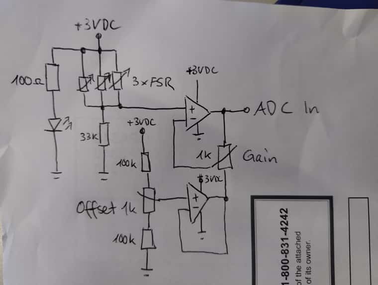
It is not yet perfect, but it works good in my "test environment". I will add at least a low pass filter somewhere in the signal line to filter out possible stepper EMF's. But i have to thinking about where and how...
EDIT: the 100 ohm resistor and the LED is not needed, it shows only if the circuit is powered...
@Woody78 Yes, that's possible with the Btn_Cmd PlugIn.
https://forum.duet3d.com/topic/22776/btncmd-dwc-plugin-customise-dwc-v01-03-05-20-09-24
@droftarts Thanks for your answer. It's a Duet2... i think at least 1.04. Have to check that.
Is it correct, that also on the 30V tolerant boards, the ADC Input reads voltages between 0V to 3.3V as 0 to 1000 (in DWC)?
I'd like to test underbed FSR's on my delta.
To tune my circuit externally, i need to know the voltage range of the z-probe ADC input.
Which voltages are needed to display the values 0 and 1000 in DWC?
@Kubunter Are there many retracts when printing the letters?
@Kubunter said in Weird partial layer shift:
So is it possible that the nozzle collides with small printing errors, leading to a shift of the Y-Axis?
That can be. But normally when that happens, the shift isn't "comming back" and remains for the rest of the print.
But nice, that you've found the problem!
@luca-Massimiliano It depends a bit how you shut off heater 1 at the end.
It can be in your slicer endcode or in stop.g in the sys folder. I recommend to write the gcode to the same place.
If you firmware is 3.3 or later, you can use the following code to shut down the heaters. Assuming it is tool0 and tool1
M568 P0 R0 S0		; shut off heaters
M568 P1 R0 S0
If your firmware is older, you have to use a G10 command.
