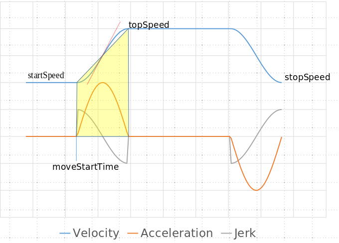
Hi, I am trying to do some progress with this. Las post from Lazarus was very clarifying and opened some ideas that I have been exploring. I would like to share with the forum the process to add some light to the maths behind the algorithm so that I can get closer to an implementation.
The first thing that called my attention from Lazarus' last post was the use of sinusoidal functions to generate an S-Curve. It triggered a lot of crazy ideas to use signal processing algorithms to work on the frequency domain, so I crushed the numbers. Unfortunately the sinusoidal waveforms do not meet the requirements.
Which are the requirements that the ideal S-Curve shall meet?:
- It shall have acceleration=0 (dv/dt =0) at the joints of the trapezoid.
- lt shall have jerk =0 at the joints of the trapezoid (dv/dt2 =0 ).
- It shall fit on the control points to the trapezoid acceleration and deceleration phases.
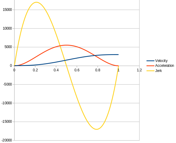
Sinusoidal waveforms can fit the trapezoid and have zero acceleration on the joints, but will fail on jerk. The maths behind this: If we use sin(t) to generate the shape, its derivative cos(t) will start and stop at 0, but its second derivative -sin(t) will not. the following graph shows an example on a Spreadsheet of Velocity, Acceleration and Jerk using sinusoidal waveforms where jerk is celarly non-zero on the trapezoidal joints:

Sadly I had to abandon the idea to use sinusoidal waves and started looking at the Bezier curves, but realized that not all Bezier curves could be fit to meet the requirements and at least a fifth order Bezier curve is required is we want to assure jerk=0 and higher orders would ensure also snap crack or pop. Since Bezier curves can be derived to infinite, it is a matter of increasing the order. However the mathematical complexity is probably not worth to compensate some effects that are physically hard to understand (I see them as harmonics of low effect). With a fifth order Bezier we can express the velocity in function of time with the following formula:
- V(t) = At^5 + Bt^4 + Ct^3 + Dt^2 + E*t + F
Where t is normalized time (from 0 to 1). And the challenge is to solve the weights (A,B,C,D,E,F). For this we apply the constraints
-
Constraint #1: dv/dt =0 at t=0 produces the first solution E=0.
-
Constraint #2: dv/dt2 =0 at t=0 produces the second solution D=0
So having E0= and D=0 warrants a jerk-free curve on the joints. -
Constraint #3: fit the curve to start speed and top speed.
-
Constraint #4,5: force dv/dt=0 and dv/dt2=0 at t=1 produce other equiations that combined will solve to the final result.
  A = -6*initialSpeed +  6*endSpeed
  B =  15*initialSpeed - 15*endSpeed
  C = -10*initialSpeed + 10*endSpeed
  D = 0
  E = 0
  F = initialSpeed
On the Acceleration Phase
initialSpeed=startSpeed
endSpeed=topSpeed
On the decceleration phase
initialSpeed=topSpeed
endSpeed=stopSpeed
The same formula applies, but if startSpeed is different that stopSpeed, the coefficients need to be recalculated to fit the trapezoid properly.
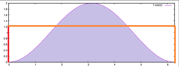
The following graph shows the graphical representation of the S Curve, acceleration and jerk using the brute force calculation on a Spreadsheet of the formula (i used startSpeed=50 and topSpeed=3000):

So these are the maths and are not so complex once understood. Now the challenge is the implementation. For that I have been reading the implementation of Movement in ReprapFirmware (and I will have to read another dozen times before I get comfortable with it and attempt to do any attempt to modify anything), so far, what I have understood is the following (and the experts can correct me if I misunderstood the code):
DDA.cpp deals with the motion planning.
DDA::Init(): would require a call to a function that calculates the coefficients of the S-Curve (A,B,C,F) each time there is a new value for "Startspeed","topSpeed" or "endSpeed".
DriveMovement.cpp
DriveMovement::CalcNextStepTime() contains the loop that define the frequency of calls to the ISR interrupts in nextCalcStepTime.
This is defined as follows for a cartesian printer:
// acceleration phase
const uint32_t adjustedStartSpeedTimesCdivA = dda.startSpeedTimesCdivA + mp.cart.compensationClocks;
nextCalcStepTime = isqrt64(isquare64(adjustedStartSpeedTimesCdivA) + (mp.cart.twoCsquaredTimesMmPerStepDivA * nextCalcStep)) - adjustedStartSpeedTimesCdivA;
I am still having trouble to understand this (it is a big challenge for me!), but looks like it is calculated as a function of A (meaning Acceleration?). If this is the case, it would be a matter of adding an "if (trajectoryPlanning=bezier) { nextCalcStepTime = a_function_of_the_variable_S_Curve_velocity_in_realtime}.
[the if... would allow to define an M code and make the feature configurable]
Another "major" challenge to reach the goal is too find a method to calculate v(t) [or (a(t)] in an efficient manner for a real-time system.
TinyG is using "Forward Difference Calculation" algorithm. Forward differencing is an efficient scheme for evaluating a polynomial at many uniform steps, but it will not work if the steps are not uniform.
Marlin is tickless, i.e., interrupts are only generated where a step (or some other event) has to be scheduled. Because of this Marlin implementation could not use TinyG approach and their solution consisted to transform the math to use fixed point values to be able to evaluate it in realtime and they implemented this portion in assembler code to be even more efficient.
In the case of Duet, I need to read further, but would appear that it is also tickless. We might explore other algorithms (probably we could not do better than Horner's method) or adopt Marlin's approach.
It's been a long post, but I would hope that it is useful and leads us to a successful implementation of a new feature that is already receiving lots of recognition by the Marlin community.
Carlos.
