@dc42 in my config.g file I have set the following:
M584 X0 Y1 Z2 E3:4 ; set drive mapping;
so normally, so will it suffice just to switch the cables from E0 to E1?
Or should I use the M584 as bellow?
M584 E4
And then afterwards M906 E1200 I80?
Posts made by campeancalin
-
RE: stepper driver for the active toolhead no longer works.posted in Tuning and tweaking
-
RE: stepper driver for the active toolhead no longer works.posted in Tuning and tweaking
@dc42 is it posssible to activate a deactivated tool using the console, without having to modify the config.g file?
Also if I want to make changes in config.g and refresh the board, will the paused print be lost? -
RE: Resume after power failure questionposted in Tuning and tweaking
Hello, @dc42 thank you but is there a more detailed documentation to it?
-
stepper driver for the active toolhead no longer works.posted in Tuning and tweaking
Is it possible to change the stepper driver for one motor without having to refresh the board? I have a long print going on and I would like not to lose it
-
Resume after power failure questionposted in Tuning and tweaking
Hello,
We recently are dealing with electrical power interruptions during very long prints. We are very interested in setting up a configuration which would help us to restart the print from where it stopped . I have in my system directory a resurrect.g file that has the following content:
; File "0:/gcodes/CARCASA FAR STANGA.gcode" resume print after print paused at 2021-05-19 11:39
G21
M140 P0 S100.0
G29 S1
T-1 P0
G92 X456.032 Y-70.905 Z144.920
G60 S1
G10 P1 S0 R0
G10 P0 S270 R270
T0 P0
M98 P"resurrect-prologue.g"
M116
M290 X0.000 Y0.000 Z0.280 R0
T-1 P0
T0 P6
; Workplace coordinates
G10 L2 P1 X0.00 Y0.00 Z0.00
G10 L2 P2 X0.00 Y0.00 Z0.00
G10 L2 P3 X0.00 Y0.00 Z0.00
G10 L2 P4 X0.00 Y0.00 Z0.00
G10 L2 P5 X0.00 Y0.00 Z0.00
G10 L2 P6 X0.00 Y0.00 Z0.00
G10 L2 P7 X0.00 Y0.00 Z0.00
G10 L2 P8 X0.00 Y0.00 Z0.00
G10 L2 P9 X0.00 Y0.00 Z0.00
G54
M106 S0.00
M116
G92 E0.00000
M83
M23 "0:/gcodes/CARCASA FAR STANGA.gcode"
M26 S16749084
G0 F6000 Z147.200
G0 F6000 X472.532 Y-20.905
G0 F6000 Z145.200
G1 F2100.0 P0
G21
M24Any help would be highly appreciated
-
RE: Tuning Macros Menus (Accel, Jerk, Retraction, Pressure Advance)posted in Tuning and tweaking
Hello @Phaedrux
Do these macros work for RRF 3.1.1?
Do these macros override the acceleration, jerk, and speed values set initially in gonfig.g?Thank you
-
RE: mirrored 3 d printed partsposted in Tuning and tweaking
Hello @mrehorstdmd ,
In the firmware I've set the homing position to max y, so I could set the slicer for the right hand coord system. I also tested the movement on the x and y axes and had to change the quadrant in which x and y move in the positive direction.
-
RE: mirrored 3 d printed partsposted in Tuning and tweaking
Do i have to set the min and max axis values via the G92 command?
-
RE: mirrored 3 d printed partsposted in Tuning and tweaking
Hello all,
Thank you all for the insight regarding this issue.It appears that I've set the y axis in clockwise direction. Is there a way to set the homing on +y axis, instead of homing to y=0?
-
RE: mirrored 3 d printed partsposted in Tuning and tweaking
Hello @bearer, it's a core XY 3d printer . Here's the config :
; Configuration file for Duet WiFi (firmware version 3)
; executed by the firmware on start-up
;
; generated by RepRapFirmware Configuration Tool v3.1.4 on Mon Oct 05 2020 11:50:08 GMT+0300 (Eastern European Summer Time); General preferences
G90 ; send absolute coordinates...
M83 ; ...but relative extruder moves
M550 P"Oscar" ; set printer name
M669 K1 ; select CoreXY mode; Network
M551 P"" ; set password
M552 S1 ; enable network
M586 P0 S1 ; enable HTTP
M586 P1 S1 ; enable FTP
M586 P2 S0 ; disable Telnet; Drives
M584 X1 Y0 Z2 E3:4 ; set drive mapping; INIT:X=0; Y=1; Z2;E3:4
M569 P0 S0 ; physical drive 0 goes backwards
M569 P1 S0 ; physical drive 1 goes backwards
M569 P2 S1 ; physical drive 2 goes FORWARDS
M569 P3 S1 ; physical drive 3 goes FORWARDS
M569 P4 S0 ; physical drive 4 goes backwardsM350 X16 Y16 Z16:16 E16:16 I1 ; configure microstepping with interpolation ; INIT- M350 X16 Y16 Z16 E16:16 I1
M92 X160.00 Y160.00 Z3200.00 E843.26:830.8 ; set steps per mm
M566 X600.00 Y600.00 Z12.00 E120.00:120.00 ; set maximum instantaneous speed changes (mm/min)set x and y to 600 from 900
M203 X6000.00 Y6000.00 Z360.00 E1200.00:1200.00 ; set maximum speeds (mm/min)
M201 X250.00 Y250.00 Z20.00 E250.00:250.00 ; set accelerations (mm/s^2)x and y 250 from 500
M906 X1100 Y1100 Z1200 E1200:1200 I80 ; set motor currents (mA) and motor idle factor in per cent changed X1200 Y1200 to X1100 Y1100
M84 S30 ; Set idle timeout
; Pressure advance
M572 D0:1 S0.05:0.05 ; enabled Pressure advance for both extruders
;M572 D0:1 S0.035:0.035; Axis Limits
M208 X0 Y0 Z0 S1 ; set axis minima
M208 X600 Y600 Z525 S0 ; set axis maxima; Endstops
M574 X1 S1 P"!xstop" ; configure active-high endstop for low end on X via pin xstop -added "! to xstop"
M574 Y1 S1 P"!ystop" ; configure active-high endstop for low end on Y via pin ystop - added"! to xstop"
M574 Z1 S2 ; configure Z-probe endstop for low end on Z; Z-Probe
M950 S0 C"duex.pwm5" ; create servo pin 0 for BLTouch
M558 P9 C"^zprobe.in" H5 F120 T6000 ; set Z probe type to bltouch and the dive height + speeds
G31 P25 X20 Y37 Z2.49 ; set Z probe trigger value, offset and trigger height- changed from 3.5 to 2.19 to -0.797,to 2.4 to 2.49
M557 X40:520 Y80:520 P20 ; define mesh grid changed S20 to P3 to P20; Heaters
M308 S0 P"bedtemp" Y"thermistor" T100000 B4138 ; configure sensor 0 as thermistor on pin bedtemp
M950 H0 C"bedheat" T0 ; create bed heater output on bedheat and map it to sensor 0
M307 H0 B0 S1.00 ; disable bang-bang mode for the bed heater and set PWM limit
M140 H0 ; map heated bed to heater 0
M143 H0 S130 ; set temperature limit for heater 0 to 130C
M308 S1 P"e0temp" Y"thermistor" T100000 B4725 C7.06e-8 ; configure sensor 1 as thermistor on pin e0temp
M950 H1 C"e0heat" T1 ; create nozzle heater output on e0heat and map it to sensor 1
M307 H1 B0 S1.00 ; disable bang-bang mode for heater and set PWM limit
M308 S2 P"e1temp" Y"thermistor" T100000 B4725 C7.06e-8 ; configure sensor 2 as thermistor on pin e1temp
M950 H2 C"e1heat" T2 ; create nozzle heater output on e1heat and map it to sensor 2
M307 H2 B0 S1.00 ; disable bang-bang mode for heater and set PWM limit; Fans
M950 F0 C"fan0" Q500 ; create fan 0 on pin fan0 and set its frequency
M106 P0 S1 H-1 ; set fan 0 value. Thermostatic control is turned off
M950 F1 C"fan1" Q500 ; create fan 1 on pin fan1 and set its frequency
M106 P1 S1 H-1 ; set fan 1 value. Thermostatic control is turned off; Tools
M563 P0 S"Tool 1" D0 H1 F0 ; define tool 0
G10 P0 X0 Y0 Z0 ; set tool 0 axis offsets
G10 P0 R0 S0 ; set initial tool 0 active and standby temperatures to 0C
M563 P1 S"Tool 2" D1 H2 F1 ; define tool 1
G10 P1 X0 Y0 Z0 ; set tool 1 axis offsets
G10 P1 R0 S0 ; set initial tool 1 active and standby temperatures to 0C; Custom settings are not defined
M912 P0 S-16.95 ; adjustment of the MCU temp read; Miscellaneous
M575 P1 S1 B57600 ; enable support for PanelDue
M911 S10 R11 P"M913 X0 Y0 G91 M83 G1 Z3 E-5 F1000" ; set voltage thresholds and actions to run on power loss
M501 ; load saved parameters from non-volatile memory -
mirrored 3 d printed partsposted in Tuning and tweaking
Hello all,
I recently came across the following problem: my parts are printed in mirrored orientation
Bellow you have a photo of the printed part In the top view , the end switches ( home for x and y ) are positioned at the top left corner. Z is being homed using a bl touch .
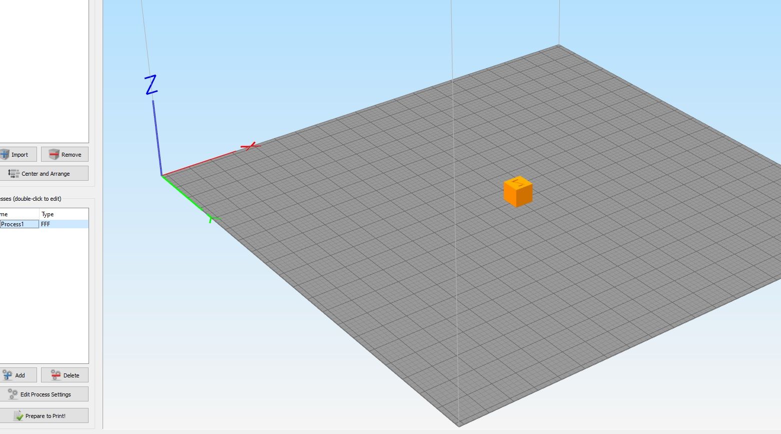
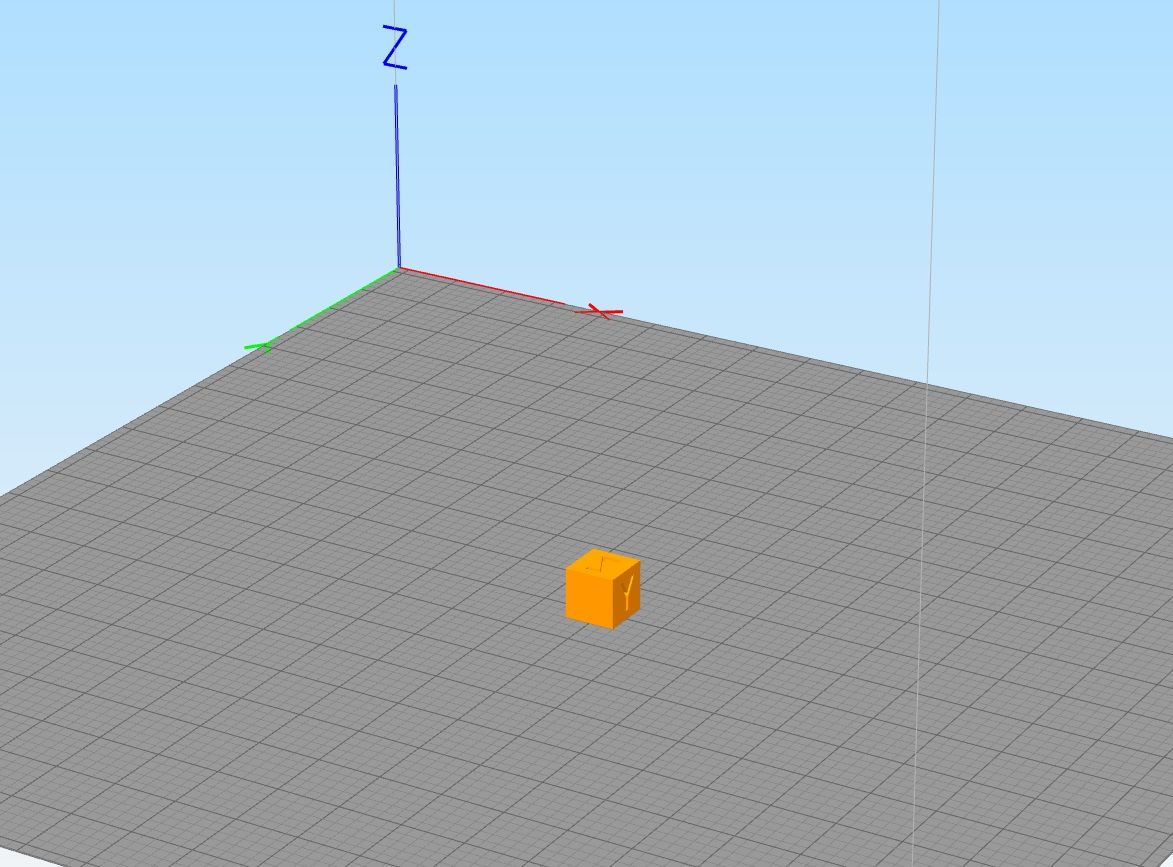
Bellow you have the position of the part in the Slicer (Simplify3d), given the orientation of the axes on the machine :


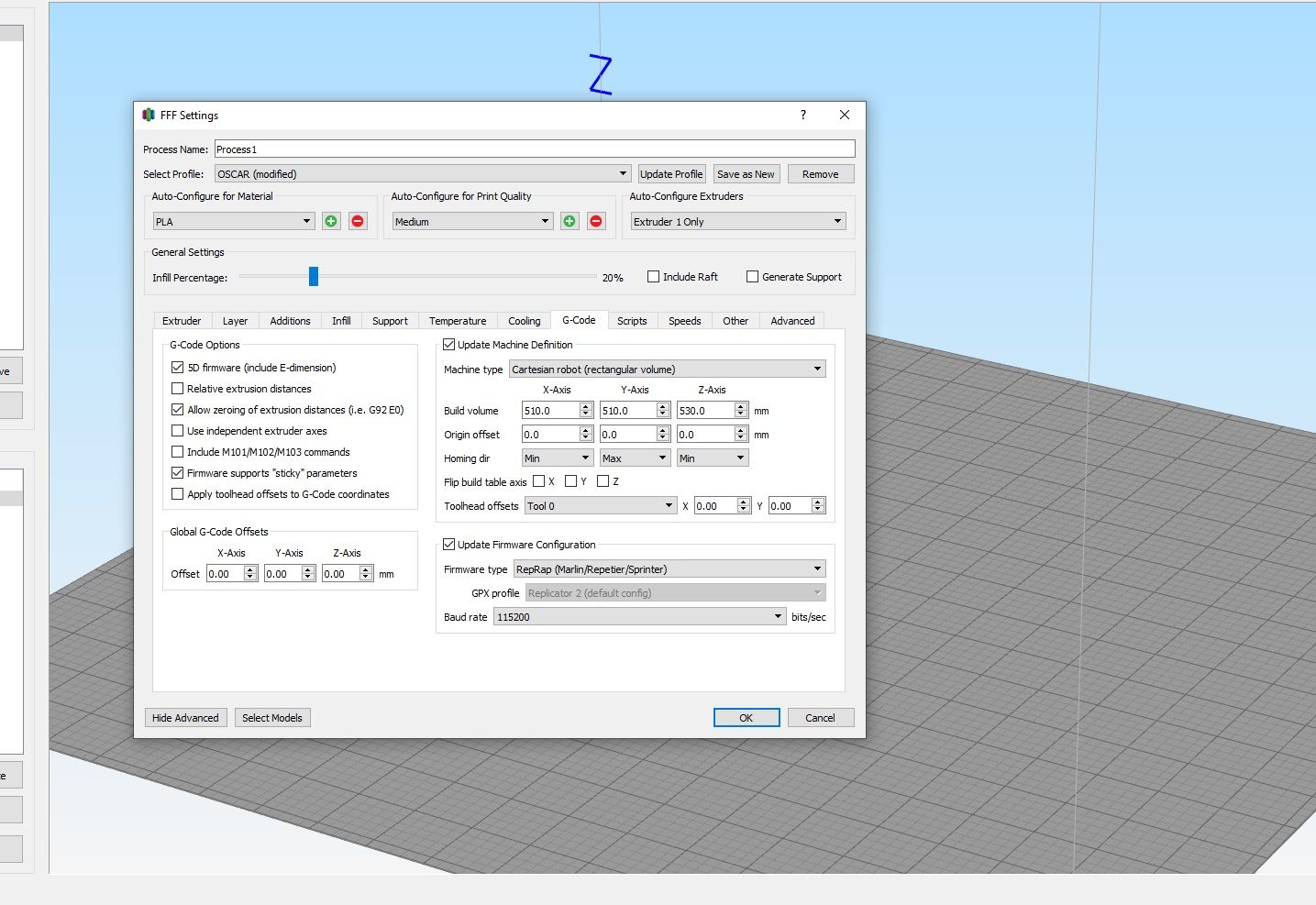
There are no axes flipped in the in the machine settings

I decided to flip the y axis , but still to no avail

-
RE: 3D printin issues on a core XY equiped with a duet wifiposted in Tuning and tweaking
@Veti No. I've PID tunned it for a max temp of 100 C
-
RE: 3D printin issues on a core XY equiped with a duet wifiposted in Tuning and tweaking
; Heaters
M308 S0 P"bedtemp" Y"thermistor" T100000 B4138 ; configure sensor 0 as thermistor on pin bedtemp
M950 H0 C"bedheat" T0 ; create bed heater output on bedheat and map it to sensor 0
M307 H0 B0 S1.00 ; disable bang-bang mode for the bed heater and set PWM limit
M140 H0 ; map heated bed to heater 0
M143 H0 S250 ; set temperature limit for heater 0 to 120C
M308 S1 P"e0temp" Y"thermistor" T100000 B4725 C7.06e-8 ; configure sensor 1 as thermistor on pin e0temp
M950 H1 C"e0heat" T1 ; create nozzle heater output on e0heat and map it to sensor 1
M307 H1 B0 S1.00 ; disable bang-bang mode for heater and set PWM limit
M308 S2 P"e1temp" Y"thermistor" T100000 B4725 C7.06e-8 ; configure sensor 2 as thermistor on pin e1temp
M950 H2 C"e1heat" T2 ; create nozzle heater output on e1heat and map it to sensor 2
M307 H2 B0 S1.00 ; disable bang-bang mode for heater and set PWM limit -
RE: 3D printin issues on a core XY equiped with a duet wifiposted in Tuning and tweaking
I have a little problem with the PID tunning. Once I've changed the values , it gives me the following error message:
M307 H1 S285Error: M307: bad model parameters
-
RE: 3D printin issues on a core XY equiped with a duet wifiposted in Tuning and tweaking
@Veti It's not a brass nozzle ; reinfoced steel. I plan on having a look at it after it's gone thru a spool of filament.
-
RE: 3D printin issues on a core XY equiped with a duet wifiposted in Tuning and tweaking
after changing the B values do I have to redo the PID tunning?
-
RE: 3D printin issues on a core XY equiped with a duet wifiposted in Tuning and tweaking
the printheads are 24V E3D V6
-
RE: 3D printin issues on a core XY equiped with a duet wifiposted in Tuning and tweaking
@Veti Bellow you have the config.g file:
; Configuration file for Duet WiFi (firmware version 3)
; executed by the firmware on start-up
;
; generated by RepRapFirmware Configuration Tool v3.1.4 on Mon Oct 05 2020 11:50:08 GMT+0300 (Eastern European Summer Time); General preferences
G90 ; send absolute coordinates...
M83 ; ...but relative extruder moves
M550 P"Oscar" ; set printer name
M669 K1 ; select CoreXY mode; Network
M551 P"" ; set password
M552 S1 ; enable network
M586 P0 S1 ; enable HTTP
M586 P1 S1 ; enable FTP
M586 P2 S0 ; disable Telnet; Drives
M584 X1 Y0 Z2 E3:4 ; set drive mapping; INIT:X=0; Y=1; Z2;E3:4
M569 P0 S0 ; physical drive 0 goes backwards
M569 P1 S0 ; physical drive 1 goes backwards
M569 P2 S1 ; physical drive 2 goes FORWARDS
M569 P3 S1 ; physical drive 3 goes FORWARDS
M569 P4 S0 ; physical drive 4 goes backwardsM350 X16 Y16 Z16:16 E16:16 I1 ; configure microstepping with interpolation ; INIT- M350 X16 Y16 Z16 E16:16 I1
M92 X160.00 Y160.00 Z3200.00 E843.26:830.8 ; set steps per mm
M566 X600.00 Y600.00 Z12.00 E120.00:120.00 ; set maximum instantaneous speed changes (mm/min)set x and y to 600 from 900
M203 X6000.00 Y6000.00 Z360.00 E1200.00:1200.00 ; set maximum speeds (mm/min)
M201 X250.00 Y250.00 Z20.00 E250.00:250.00 ; set accelerations (mm/s^2)x and y 250 from 500
M906 X1100 Y1100 Z1200 E1200:1200 I80 ; set motor currents (mA) and motor idle factor in per cent changed X1200 Y1200 to X1100 Y1100
M84 S30 ; Set idle timeout
; Pressure advance
M572 D0:1 S0.05:0.05 ; enabled Pressure advance for both extruders; Axis Limits
M208 X0 Y0 Z0 S1 ; set axis minima
M208 X600 Y600 Z525 S0 ; set axis maxima; Endstops
M574 X1 S1 P"!xstop" ; configure active-high endstop for low end on X via pin xstop -added "! to xstop"
M574 Y1 S1 P"!ystop" ; configure active-high endstop for low end on Y via pin ystop - added"! to xstop"
M574 Z1 S2 ; configure Z-probe endstop for low end on Z; Z-Probe
M950 S0 C"duex.pwm5" ; create servo pin 0 for BLTouch
M558 P9 C"^zprobe.in" H5 F120 T6000 ; set Z probe type to bltouch and the dive height + speeds
G31 P25 X20 Y37 Z2.32 ; set Z probe trigger value, offset and trigger height- changed from 3.5 to 2.19 to -0.797,to 2.23to 2.316
M557 X40:520 Y80:520 P20 ; define mesh grid changed S20 to P3 to P20; Heaters
M308 S0 P"bedtemp" Y"thermistor" T100000 B4138 ; configure sensor 0 as thermistor on pin bedtemp
M950 H0 C"bedheat" T0 ; create bed heater output on bedheat and map it to sensor 0
M307 H0 B0 S1.00 ; disable bang-bang mode for the bed heater and set PWM limit
M140 H0 ; map heated bed to heater 0
M143 H0 S250 ; set temperature limit for heater 0 to 120C
M308 S1 P"e0temp" Y"thermistor" T100000 B4138 ; configure sensor 1 as thermistor on pin e0temp
M950 H1 C"e0heat" T1 ; create nozzle heater output on e0heat and map it to sensor 1
M307 H1 B0 S1.00 ; disable bang-bang mode for heater and set PWM limit
M308 S2 P"e1temp" Y"thermistor" T100000 B4138 ; configure sensor 2 as thermistor on pin e1temp
M950 H2 C"e1heat" T2 ; create nozzle heater output on e1heat and map it to sensor 2
M307 H2 B0 S1.00 ; disable bang-bang mode for heater and set PWM limit; Fans
M950 F0 C"fan0" Q500 ; create fan 0 on pin fan0 and set its frequency
M106 P0 S1 H-1 ; set fan 0 value. Thermostatic control is turned off
M950 F1 C"fan1" Q500 ; create fan 1 on pin fan1 and set its frequency
M106 P1 S1 H-1 ; set fan 1 value. Thermostatic control is turned off; Tools
M563 P0 S"Tool 1" D0 H1 F0 ; define tool 0
G10 P0 X0 Y0 Z0 ; set tool 0 axis offsets
G10 P0 R0 S0 ; set initial tool 0 active and standby temperatures to 0C
M563 P1 S"Tool 2" D1 H2 F1 ; define tool 1
G10 P1 X0 Y0 Z0 ; set tool 1 axis offsets
G10 P1 R0 S0 ; set initial tool 1 active and standby temperatures to 0C; Custom settings are not defined
M912 P0 S-16.95 ; adjustment of the MCU temp read; Miscellaneous
M575 P1 S1 B57600 ; enable support for PanelDue
M911 S10 R11 P"M913 X0 Y0 G91 M83 G1 Z3 E-5 F1000" ; set voltage thresholds and actions to run on power loss
M501 ; load saved parameters from non-volatile memory