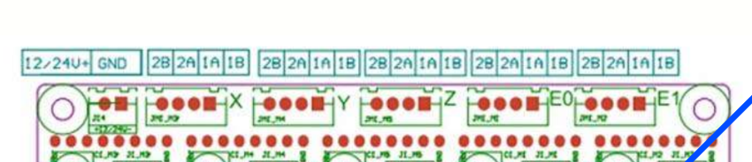
Hi, I am in the process of installing duet 2 wifi in my Artillery Genius.
I have most everything working, except the hotend cooling fan, which unlike the part cooling fan did not have a separate header on the original MKS Gen L board.
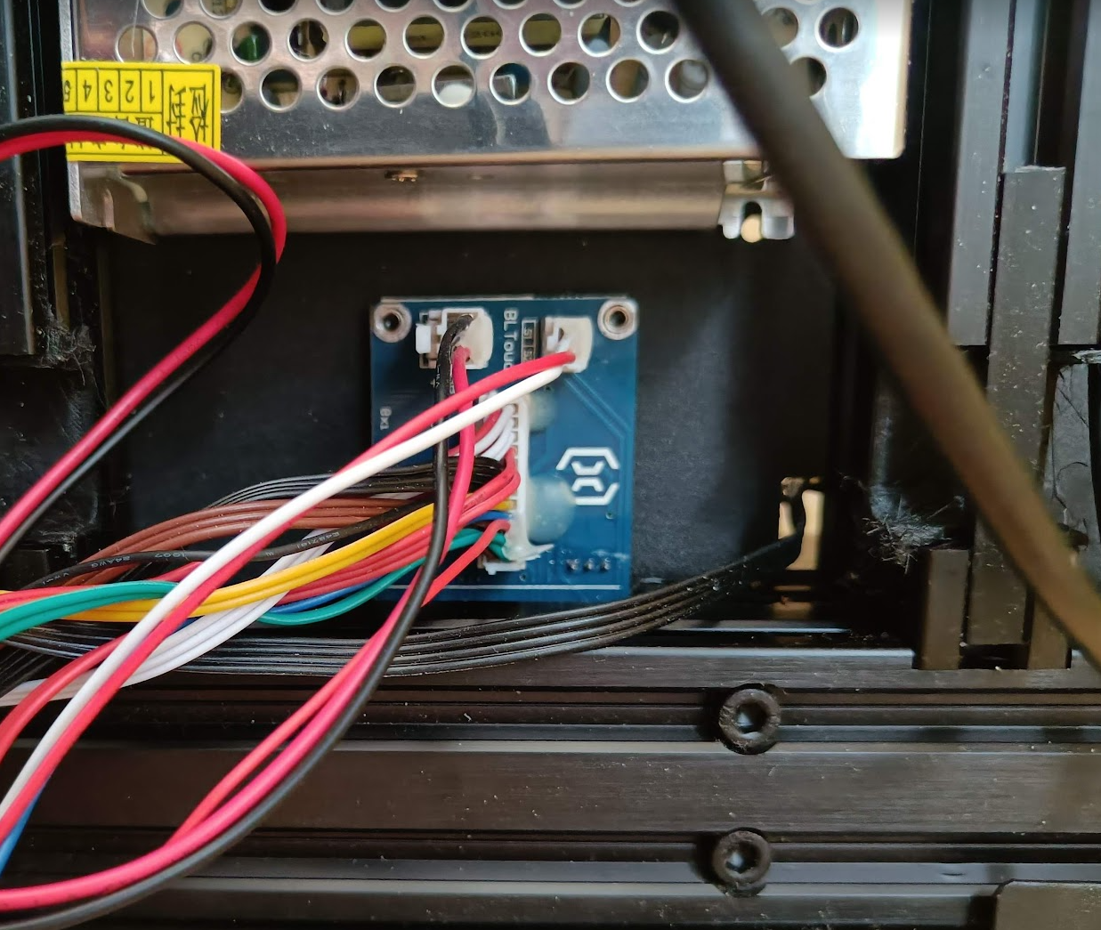
So the signal path to the fan is set up like this: main board -> carriage connector PCB -> Z ribbon cable -> X connector PCB -> X ribbon cable -> extruder connector PCB -> fan
I saw online somewhere that its run from one of the heatbed connectors, but that does not tell me enough (very limited electronical knowledge).
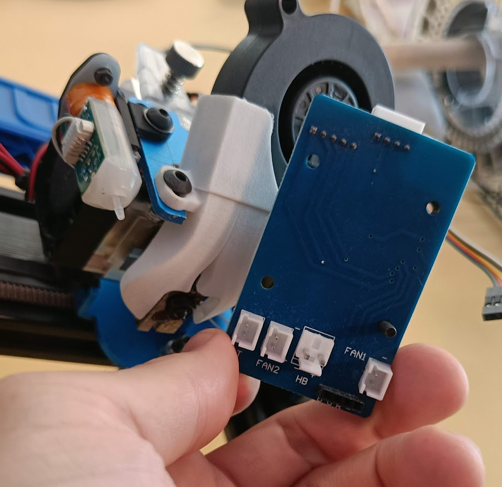
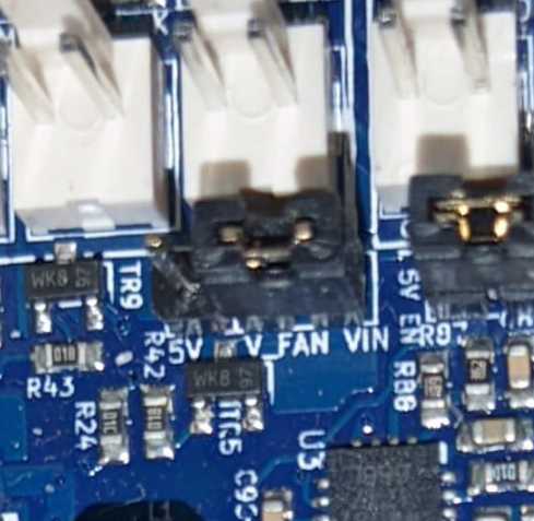
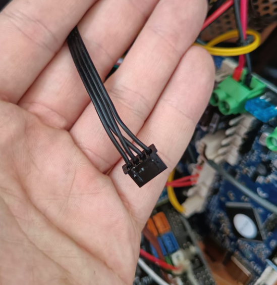
I found a lone wire that has continuity with both the - and + leads of the fan2 connection on the extruder PCB seen above. It confused me, how can it have continuity with both? Am i interpreting the reading wrong?
I tried looking up the pinout of the carriage PCB pictured above. but could only find pinouts for the ribbons, not this board.
Basically, i have absolutely no clue anymore haha. I would like some help.
One alternative would be to just run a wire from the fan to the duet, but it would be much less elegant, and understanding what I am missing here would help me learn.
Thanks in advance!!
")