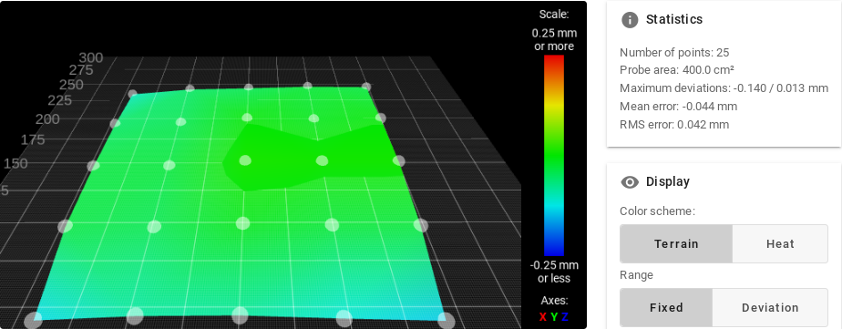
Ian, Many thanks, all seems to work just fine, onwards??
Posts made by Bridge Of Don
-
RE: Auto matic Levelling Error
-
RE: Auto matic Levelling Error
@droftarts said in Auto matic Levelling Error:
'General preferences' section. I have asked @chrishamm, and he's agreed to move it in the new configuration tool to earlier in config.g, so it doesn't catch people out. Thanks for the idea!
Ian,
I'd hardly call it an 'idea' !!BTW just feel free to treat me as your 'tame idiot' to do any testing .. . . .
I'll let you know how it all goes , surely now all will be 'plug-n-play' for the other users at the 'Shed'?
Thanks again
Alan
-
RE: Auto matic Levelling Error
@droftarts said in Auto matic Levelling Error:
Yes, it does. But your issue is because there's an error in your config.g, caused by M671 (which defines the leadscrew position) being earlier in config.g than M669, which defines the kinematics.
Order dependency
M671 must come later in config.g than any command that changes the kinematics, e.g. M667 or M669.By running config.g again with M98, the kinematics are already set from running config.g at startup, so M671 is then recognised.
There's no reason to have the Kinematics section at the end; I usually have it as one of the first things in config.g
You also have two M208 commands, at line 44 and 48; the latter one sets X and Y smaller than the earlier one.
Ian
Ian
That will be the issue then!
AND I'd read the comment about M671 being after M669
I think that the kinematics was 'at the end' from the RepRap ? so was trying to copy/paste the levelling into the area for the 'configure drives' not realising I had messed up . ..I'd not spotted that I had M208 TWICE, I need to see how far in the Y direction we can really now travel. We changed the location clips from the side to hold the glass at front and rear (330 x 330) so we maybe need to adjust the zero on the Y to avoid those at the front and then shorten the Y travel.
Looks like I'll be loading a revised CONFIG on Thursday cos it's not weather to do anything else!!
Alan
-
RE: Auto matic Levelling Error
@Bridge-Of-Don said in Auto matic Levelling Error:
Thanks for swift reply, some were there from the 'RepRap' set-up and I was reluctant to remove anything in case it went to a 'ball of chalk'G29 ; call mesh bed compensation
This bit was there 'initially' so i just left it , not sure what it did
The same applies to bit about 'coarse home' TBH I didn't even spot it was doing the same thing 'twice' !
I 'cheated' and added the levelling (rows 30 to 37) into 'Home All' & Home Z' so that it would do it during the first pass.
When does the DUET run the 'config' file? I assumed at 'power-up', but seems not?
I had a few reads of the duet Documention and reckone dI had it sussed
Maybe all I need to do then is to remove row 6 from the BED, so it is not calling the bed mesh?
@Bridge-Of-Don said in Auto matic Levelling Error:
G29 ; call mesh bed compensation
I'd also thought (maybe in error?) that i'd need to get the bed 'about' correct height (row 28 in Home All ) before probing Left & Right to get it level, and then to be safe I checked that the nozzle was correct distance from the bed (row 37)
I can't make any changes until Thursday AM as printer is in the 'Men's Shed'
Alan
-
RE: Auto matic Levelling Error
Aye not a problem
BED
###########; bed.g ; called to level the bed ; ; generated by RepRapFirmware Configuration Tool v3.5.0 on Wed May 29 2024 09:26:56 GMT+0100 (British Summer Time) G29 ; call mesh bed compensation ;Extra for levelling oct 2024 G28 ; home G30 P0 X20 Y150 Z-99999 ; probe near LHS leadscrew, half way along Y axis G30 P1 X300 Y150 Z-99999 S2 ; probe near RHS leadscrew and calibrate 2 motors ;ADDED the whole of HOME Z into this section to reset the centre G1 X200 Y150 F6000 ; go to bed centre G30 ; probe the bed
CONFIG
#############; Configuration file for RepRapFirmware on Duet 2 WiFi ; executed by the firmware on start-up ; ; generated by RepRapFirmware Configuration Tool v3.5.0 on Wed May 29 2024 09:26:56 GMT+0100 (British Summer Time) ; edits by Alan Tulloch 26th June 2024 ; General G90 ; absolute coordinates M83 ; relative extruder moves M550 P"Bridge" ; set hostname ; Accessories M575 P1 S0 B57600 ; configure PanelDue support ; Network M552 S1 ; configure WiFi adapter M586 P0 S1 ; configure HTTP ;############################## ; Smart Drivers for common Z drive all AXES reversed 29th May M569 P0 S0 D2 ; driver 0 goes backwards (X axis) M569 P1 S0 D2 ; driver 1 goes backwards (Y axis) M569 P2 S0 D2 ; driver 2 goes backwards (Z axis, both and LHS if running levelling) M569 P3 S1 D2 ; driver 3 goes forwards (extruder 0) M569 P4 S0 D2 ; driver 4 goes backwards (RHS Z axis) ; Motor Idle Current Reduction M906 I30 ; set motor current idle factor M84 S30 ; set motor current idle timeout ; Axes ;M584 X0 Y1 Z2 E3; set axis mapping with common Z drive, extruder on 3 ;Extra for two Z drives October 2024 M584 X0 Y1 Z2:4 E3; two Z motors connected to driver 2 top socket(left motor) and driver 4 E1 (right motor) M350 X16 Y16 Z16 I1 ; configure microstepping with interpolation M906 X800 Y800 Z800 ; set axis driver currents M92 X80 Y80 Z400 ; configure steps per mm M208 X0:320 Y0:320 Z0:300 ; set minimum and maximum axis limits increased from 300 x 300 4th July 2024 ;Extra section for levelling, M671 X-90:410 Y160:160 S3 ; position of leadscrew/bed pivot point at left and right of X axis, maximum correction three mm M208 X0:300 Y0:300 ; X carriage moves from zero to 300 (ensures probe is above the table on LHS, and doesn't collide with frame at RHS) , Y bed goes from 0 to 310. Probe ~40mm to left of nozzle ;##############################;; ; start of original ; Smart Drivers ALL reversed 29th May ;M569 P0 S0 D2 ; driver 0 goes backwards (X axis) ;M569 P1 S0 D2 ; driver 1 goes backwards (Y axis) ;M569 P2 S0 D2 ; driver 2 goes backwards (Z axis) ;M569 P3 S1 D2 ; driver 3 goes forwards (extruder 0) ; Motor Idle Current Reduction ;M906 I30 ; set motor current idle factor ;M84 S30 ; set motor current idle timeout ; Axes ;M584 X0 Y1 Z2 ; set axis mapping ;M350 X16 Y16 Z16 I1 ; configure microstepping with interpolation ;M906 X800 Y800 Z800 ; set axis driver currents ;M92 X80 Y80 Z400 ; configure steps per mm ;M208 X0:320 Y0:320 Z0:300 ; set minimum and maximum axis limits incresed from 300 x 300 4th July ;end of original config M566 X900 Y900 Z12 ; set maximum instantaneous speed changes (mm/min) M203 X6000 Y6000 Z180 ; set maximum speeds (mm/min) M201 X500 Y500 Z20 ; set accelerations (mm/s^2) ; Extruders M584 E3 ; set extruder mapping M350 E16 I1 ; configure microstepping with interpolation M906 E1000 ; set extruder driver currents M92 E420 ; configure steps per mm M566 E120 ; set maximum instantaneous speed changes (mm/min) M203 E3600 ; set maximum speeds (mm/min) M201 E250 ; set accelerations (mm/s^2) ; Kinematics M669 K1 ; configure CoreXY kinematics ; Probes M558 K0 P9 C"^zprobe.in" H5 F120 T6000 ; configure BLTouch probe via slot #0 this was ^exp.thermistor3 changed from info on Duet Forum G31 P500 X-38 Y-5 Z1.7 ; set Z probe trigger value, offset and trigger height was 0.7 initially, changed from 1.6 to 1.75 on 26th June, then 1.67 on 24th july M950 S0 C"exp.heater3" ; create servo #0 for BLtouch ; Endstops M574 X1 P"!xstop" S1 ; configure X axis endstop swapped to reverse logic 29th May M574 Y1 P"!ystop" S1 ; configure Y axis endstop swapped to reverse logic 29th May M574 Z2 S2 ; configure Z axis endstop ; Tools M563 P0 D0 H1 F0 ; create tool #0 M568 P0 R0 S0 ; set initial tool #0 active and standby temperatures to 0C
HOME ALL
##############; homeall.g ; called to home all axes ; ; generated by RepRapFirmware Configuration Tool v3.5.0 on Wed May 29 2024 09:27:02 GMT+0100 (British Summer Time) ; increase Z G91 ; relative positioning G1 H2 Z5 F6000 ; move Z relative to current position to avoid dragging nozzle over the bed G90 ; absolute positioning ; home XY var xTravel = move.axes[0].max - move.axes[0].min + 5 ; calculate how far X can travel plus 5mm var yTravel = move.axes[1].max - move.axes[1].min + 5 ; calculate how far Y can travel plus 5mm G91 ; relative positioning G1 H1 X{-var.xTravel} Y{-var.yTravel} F600 ; coarse home G1 H1 X{-var.xTravel} F600 ; coarse home in the -X direction G1 H1 Y{-var.yTravel} F600 ; coarse home in the -Y direction G1 X5 Y5 F6000 ; move back 5mm G1 H1 X{-var.xTravel} Y{-var.yTravel} F300 ; fine home G1 H1 X{-var.xTravel} F300 ; fine home in the -X direction G1 H1 Y{-var.yTravel} F300 ; fine home in the -Y direction G90 ; absolute positioning ; home Z var xCenter = move.compensation.probeGrid.mins[0] + (move.compensation.probeGrid.maxs[0] - move.compensation.probeGrid.mins[0]) / 2 - sensors.probes[0].offsets[0] var yCenter = move.compensation.probeGrid.mins[1] + (move.compensation.probeGrid.maxs[1] - move.compensation.probeGrid.mins[1]) / 2 - sensors.probes[0].offsets[1] G1 X160 Y150 F6000 ; Put nozzle to bed centre this was {var.xCenter} Y{var.yCenter} G30 ; probe the bed ;Extra for levelling oct 2024 G30 P0 X20 Y150 Z-99999 ; probe near LHS leadscrew, half way along Y axis G30 P1 X300 Y150 Z-99999 S2 ; probe near RHS leadscrew and calibrate 2 motors ;ADDED the whole of HOME Z into this section to reset the centre G1 X200 Y150 F6000 ; put probe to bed centre (probe ~40 to left of nozzle) G30 ; probe the bed
Hope this helps?
Alan
-
Auto matic Levelling Error
Progress has been made and we have managed to change the wiring (two Z drives) and up-date the following files
Bed
Config,
HomeALL,
Home Z etcALLworks well EXCEPT after power off & on when we get the following
########
16/10/2024, 10:44:02 Connected to 192.168.1.nnn
16/10/2024, 10:44:52 G28
Error: This kinematics does not support auto-calibration
#######If I open, close and run the Config file (without any changes) then all seems OK, as per below
16/10/2024, 10:45:59 Upload of config.g successful after 0s
16/10/2024, 10:46:04 M98 P"config.g"
HTTP is enabled on port 80
16/10/2024, 10:47:10 G28
Leadscrew adjustments made: -1.521 1.791, points used 2, (mean, deviation) before (0.135, 0.928) after (0.000, 0.000)My question is how to force Config to run at start up or what do I need to add as a MACRO do to avoid the 'initial' error?
Trying to make this 'idiot' proof.
I guess I've missed a step?
Alan
-
RE: Sporadic Temperature Changes
@Bridge-Of-Don said in Sporadic Temperature Changes:
We took the multi plug fitted at the themister apart and one of the two connectors just 'fell-out' and no real force to push back in, so hopefully that was the issue, only time will tell!?
Alan
Well several prints later and the temperature does seem to be 'rock steady' so another of the teething problems crossed off the list!!
-
RE: Sporadic Temperature Changes
We took the multi plug fitted at the themister apart and one of the two connectors just 'fell-out' and no real force to push back in, so hopefully that was the issue, only time will tell!?
Alan
-
RE: Sporadic Temperature Changes
Many thanks for all the replies.
I was unsure if what I was seeing was real or an artefact.
I'm pretty used t intermittent faults as drive a 90's car so loads of issues around the connectors to the electonic dashboard etc.I'll re-make the wire up and report back, hopefully with a positive result, but as it doesn't always spike , who knows!
I do like the DWC as a user interface, much better than a 4" LCD screen, abilty to view progress and monitor things makes life easier.
Alan
-
RE: Sporadic Temperature Changes
Many thanks for all the replies.
I was unsure if what I was seeing was real or an artefact.
I'm pretty used to intermittent faults as drive a 90's car so loads of issues around the connectors to the electronic dashboard etc.I'll re-make the wire up and report back, hopefully with a positive result, but as it doesn't always spike , who knows!
I do like the DWC as a user interface, much better than a 4" LCD screen, abilty to view progress and monitor things makes life easier.
Alan
-
Sporadic Temperature Changes
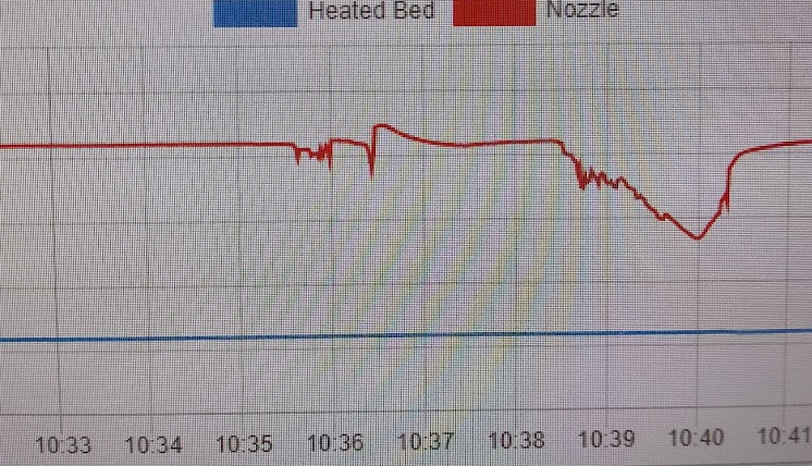
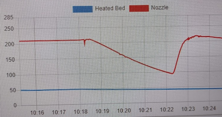
We have had a couple of times with the DWC reporting a temperature error and unsure if they are real, in some cases it turned off the heater as a 'fault' but other times no fault and nothing obvious.
The first image shows a fault, not sure if the fault was at the first small excursion 10:35:30 or a minute later on? I'm pretty sure that at 10:38 the heater was turned off (I know should have viewed/copied the fault log
the second image shows a similar blip just before print completed, 10:18:10, which might be the filament being pulled back so less/no material to melt so really the temperature should have had a small increase? then followed by a slow cool down when the heater is turned off at 10:18:30.
Any hints and tips will be helpful, we are considering rewiring the sensor as there a number of solder joints/connectors around the nozzle.
-
RE: G-code trouble, filament completely retracts
@dc42 said in G-code trouble, filament completely retracts:
@Bridge-Of-Don said in G-code trouble, filament completely retracts:
We are using 'AstroPrint' as a method of slicing and it appears to use 'CURA
It's a feature of Cura that even if you set it to use relative extrusion, it switches back to absolute extrusion before running code that you supplied in the slicer configuration. So, unless this has been changed, you will need to include M83 in your slicer end gcode.
Been away for a short while and nobody else seems willing, but I found that there is an option to set the 'Start' & 'End' code within AstroPrint (and I guess CURA?) so it will always use those bespoke settings for our printer.
This seems to have cured the issue as simply added the M83 command , and whilst there tidied/edited a few of the deafult settings to make for a cleaner start and stop.
Our bespoke ending code now looks like this
G4 ; Wait
M220 S100 ; Reset Speed factor override percentage to default (100%)
M221 S100 ; Reset Extrude factor override percentage to default (100%)
G91 ; Set coordinates to relative
M83 ; RELATIVE extrusion mode
G1 F1800 E-3 ; Retract filament 3 mm to prevent oozing
G1 F3000 Z20 ; Move Z Axis up 20 mm to allow filament ooze freely
(although this still gets a string, which we can live with)
G90 ; Set coordinates to absolute
G1 X0 Y280 F1000 ; Move extruder to the back for easy print removal
M84 ; Disable stepper motors
; End of GCode
M82 ;absolute extrusion mode
M104 S0
;End of Gcode -
RE: G-code trouble, filament completely retracts
@dc42
Yes now in the clear light of day I see the issue, the commented text from the slicing programme is wrong (in italics)it is exactly the same issue as the initial post had , sorry to waste folk's time
; End G-code
G4 ; Wait
M220 S100 ; Reset Speed factor override percentage to default (100%)
M221 S100 ; Reset Extrude factor override percentage to default (100%)
G91 ; Set coordinates to relative,just realised that this (G91) does not affect/alter the extruder/filament setting!!
This line below is the problem as crucially as the E values are still in absolute
G1 F1800 E-3 ; Retract filament 3 mm to prevent oozingIn reality for this item it means pull the filament back to -3mm and as Extruder is still in 'absolute' it will try and rewind about four feet!!
I dont think I need to set to relative as it has already pulled five mm back, but will not to much harm to add a line of code.
G1 F3000 Z20 ; Move Z Axis up 20 mm to allow filament ooze freely
G90 ; Set coordinates to absoluteNot sure how I go about flagging this as an error within the slicing programme?
-
RE: G-code trouble, filament completely retracts
@Bridge-Of-Don said in G-code trouble, filament completely retracts:
G1 X107.346 Y121.488 E1285.51944
G1 X107.979 Y120.99 E1285.5342
M204 S5000
M205 X30 Y30
G0 F7200 X108.124 Y121.135
;TIME_ELAPSED:2422.346628
G1 F2400 E1280.5342
M140 S0Apologies , it doesn't do retract five mm just that the E value decreases by five mm so I assumed that would pull it back by five mm, not sure why it then does another 3mm at the end of print/move away? ? ??
but yes i'll dig into how to adjust this to 'relative' rather than me manually re-doing the G Code
-
RE: G-code trouble, filament completely retracts
We are using 'AstroPrint' as a method of slicing and it appears to use 'CURA', this is for a TRON XY printer
initial section is this . . . . .
;FLAVOR:Marlin
;TIME:6666
;Filament used: 0m
;Layer height: 0.1;Generated with Cura_SteamEngine master
M140 S60
M105
M190 S60
M104 S210
M105
M109 S210
M82 ;absolute extrusion mode NB NO M83 code anywhere in the code
; Start G-code
G28 ; Home all axes
G92 E0 ; Reset ExtruderAt the end of the print the filament would appear to only need to reverse by five mm BUTdrive keeps running for quite some time and the drive wheel spits the filament out , so about 50mm and some.....
I've marked the last two moves of filament in bold
Note that I added the semi-colon before the G4 WAIT command to try and avoid any issues but still it pauses whilst reversing the extruder(and melts the object) before moving extruder away (actually 255 towards back of bed)
What am I missing??
M204 S500
M205 X20 Y20
G1 F1800 X104.431 Y127.059 E1285.40183
G1 X105.005 Y124.804 E1285.44449
G1 X105.999 Y122.97 E1285.48273
G1 X107.346 Y121.488 E1285.51944
G1 X107.979 Y120.99 E1285.5342
M204 S5000
M205 X30 Y30
G0 F7200 X108.124 Y121.135
;TIME_ELAPSED:2422.346628
G1 F2400 E1280.5342
M140 S0
M204 S4000
M205 X20 Y20
M107
; End G-code
;G4 ; Wait
M220 S100 ; Reset Speed factor override percentage to default (100%)
M221 S100 ; Reset Extrude factor override percentage to default (100%)
G91 ; Set coordinates to relative
G1 F1800 E-3 ; Retract filament 3 mm to prevent oozing
G1 F3000 Z20 ; Move Z Axis up 20 mm to allow filament ooze freely
G90 ; Set coordinates to absolute
G1 X0 Y255.0 F1000 ; Move Heat Bed to the front for easy print removal
M84 ; Disable stepper motors
; End of GCode
M82 ;absolute extrusion mode
M104 S0
;End of Gcode -
RE: BLT function
@Bridge-Of-Don
I am happy to report that we have today successfully manged to print off a small 'cube'.
We still need to fine tune the heaters both on control (to prevent overshoot) and actual temperature but at least it functions.
We used the 'AstroPrint' web based slicing option and downloaded the G-codes to the PC then 'uploaded' them to DWC, maybe not the most elegant of solutions but it works.
We like the ability to 'fine tune' the slicing within the 'AstroPrint' as hopefully we will learn as we go-along.I'm away again for a week, then home then away, so will have nowt to report for a little while.
-
RE: BLT function
@droftarts said in BLT function:
@Bridge-Of-Don said in BLT function:
it already has wiring from the 'BED HEATER' to the SSR
If that's the way it was wired already, then yes, the config.g is still a bit wrong. The bed heater 'traditionally' uses sensor 0 and heater 0, and the first hot end as sensor 1 and heater 1 (slightly confusing because this becomes 'Tool 0').
I think there's another error; from your picture in this post https://forum.duet3d.com/post/339699 it looks like the hot end heater is connected to e0heat (two white wires that go through the back panel), not e1heat:
The hot end thermistor is, I guess, the yellow and white cables connected to e0temp. I'm not sure why it's reading -273C, when I think you said you measured 130000 ohms. Perhaps you changed something else? I think the thermistors and heaters should be set as:
; Sensors M308 S0 P"bedtemp" Y"thermistor" A"Heated Bed" T100000 B3950 ; configure sensor #0 M308 S1 P"e0temp" Y"thermistor" A"Nozzle" T100000 B4388 C7.06e-8 ; configure sensor #1 ; Heaters M950 H0 C"bedheat" T0 ; create heater #0 ... M950 H1 C"e0heat" T1 ; create heater #1
I also notice you have the two Z motors connected to the Z axis motor connector. That's fine, because they will be synchronised and work together, but you could connect one of the motor to the spare E1 motor output. This would allow you to level the bed, at least across the X axis, using the BLTouch. This is how I have my TronXY set up currently (at least until I change it for three motors and a kinematic bed). See https://docs.duet3d.com/en/User_manual/Connecting_hardware/Z_probe_auto_levelling
But maybe one step at a time...!Ian
I'll change the config to match this latest from yourself,
I reckon that it is better to stick with the 'traditional' wiring arrangement
the multi plug (yellow/white) is in e0temp, and are broken off up at extruder hence the 'open circuit'....maybe not a great previous photo?
this is a 'square-on' view to show plugged into E0 Temp & E0 Heater
the two thicker white wires do eventually appear at the extruder, in different colour(s)As for fancy bed levelling I'm happy to stick with the two Z motors in synch and if needed it is a simple matter of using a test block at each side to 're-level' if they get out of synch, so aye 'one step at a time'
Alan
-
RE: BLT function
@droftarts
Ian, by 'fudge' I meant connecting the heated bed to a different 'output' it already has wiring from the 'BED HEATER' to the SSR and so I'd rather leave that as it is, saves (over)loading the Duet board and simpler to swap a SSR than a DuetI can check the SSR specs as well to see how fast it can be switched, especially if using PWM will give a more consistent temperature across the bed....
Not sure about the power supply's spec (and away from the shed now for a few weeks) but I assume that if it was working previously then I'll leave alone?
If not enough supply amps then I'm sure i have some Switched mode supplies 'lurking' in garage.
We greatly appreciate the help given so far!!!
Alan
-
RE: BLT function
Progress
ALL the X, Y & ALL homing work, I had to add H2 to a few places at the end of each routine, maybe not 'elegant' but fixed error messages
; decrease Z again
G91 ; relative positioning
G1 H2 Z-5 F6000 ; move Z relative to current position
G90 ; absolute positioningStill to fix the wiring for nozzle thermistor but at least the sensors are correct and the temperature reading moves with the sensor (if I swap them), so maybe a blessing that one wire was broken?
Alan
-
RE: BLT function
@droftarts said in BLT function:
both the thermistors are sitting at around 130000 Ohm when at room temp
That probably means room temperature is about 20C. The T value is the resistance at 25C.
Ref the text "e1heat", should this read "bed"? just for clarity going forward?
I guess the output is controlling a Solid State Relay (SSR), which turns the bed on and off? If so, you can use either, as the SSR shouldn't draw very much current. If you do change it to 'bed', you'll need to move the wires to the SSR to the heated bed output.
Ian
Ian
Aye the heated bed has a stonking big SSR to control it and it is wired into the Bed output, so it will have to be on/off rather than anything fancy like PWM?
although it switches the 'negative' supply?!I think I'd be happier changing this to the bed output connection as per image? as then it makes life simpler for anybody trying to follow what we have fixed/corrected, rather than fudged?
@droftarts said in BLT function:
M950 H1 C"e1heat" T1 ; create heater #1
I assume the text should be
M950 H1 C"bedheat" T1 ; create heater #1
so that this controls the correct output for the bed if using the 'High Current Heated Bed'?
This is an example of the wiring that needs 'tidied'
PS I'm glad that it wasn't just my wrong doing about the 'default config'
Thanks againAlan