@dc42 Ah! Thank you. I'll mess with that.
Posts made by benha
-
Chamber Heater Controlposted in General Discussion
Hi.
I have a large chamber volume, and it takes a fairly long time for it to come up to temperature. I've been unable to get the DWC to successfully control it, because it times out before noticing an appreciable difference in temperature. Even the PID tuning routine does this. Is there a way to configure a heater as "best effort" or something so it doesn't abort the print if the temp isn't achieved?
-Ben
-
RE: Mesh Bed Leveling expected behaviorposted in General Discussion
Ok. Made these changes and I'm still having issues.
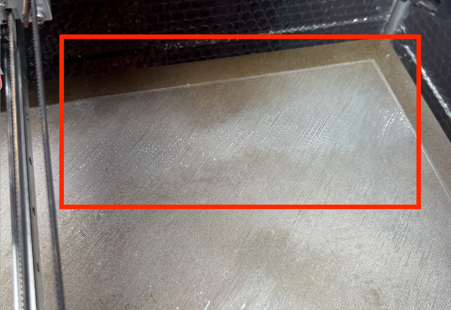
As you can see in the attached image, the layer deposition in the back corner of the plate is poor. To my eye it seems the only explanation is that the gap between the nozzle and the bed is widening, resulting in poor bed adhesion, and also gaps between the filament lines.
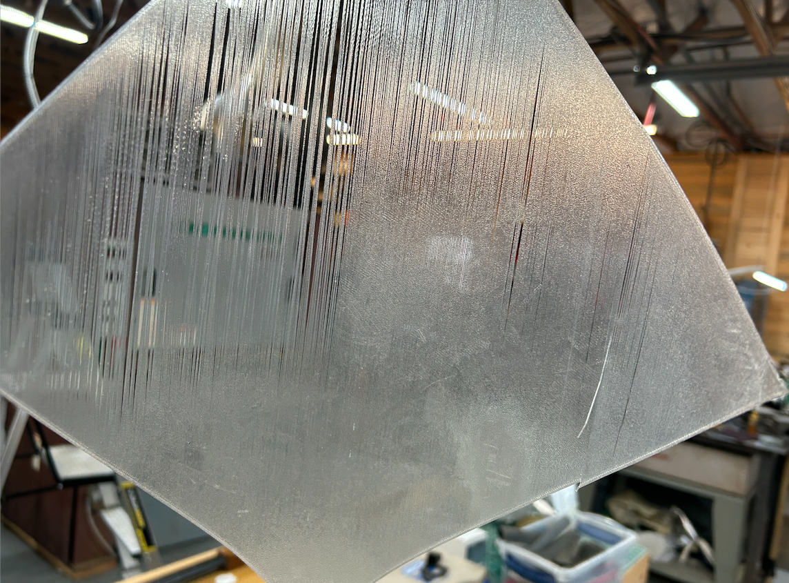
When I remove this from the plate, I see some areas where things are fully fused into a sheet, and others where they're not. Again, the only thing I can think of to explain this is that in bed areas which are closer to the nozzle as it prints there's more squeeze forcing things together, and in other areas the nozzle is further away resulting in this issue.
Thoughts?
-
RE: Mesh Bed Leveling expected behaviorposted in General Discussion
Thank you! Let me mess with this and see if I can get things going correctly. I'm out of town for a few days but I'll revert back when I've tested it.
The Orth. Axis Comp. eval / tuning was something the Railcore setup guide recommended. Intuitively it makes sense that you're not going to have perfect perpendicularity between the X and Y axis mechanicals, right? I mostly print engineering parts so getting things to print angles in the x-y plane as correctly as possible is important to me.
-
RE: Mesh Bed Leveling expected behaviorposted in General Discussion
Ah. Right. Took me a minute to figure out which files you were talking about!
-
RE: Mesh Bed Leveling expected behaviorposted in General Discussion
Thanks for taking an interest! This is a Railcore ZLT I built several years ago.
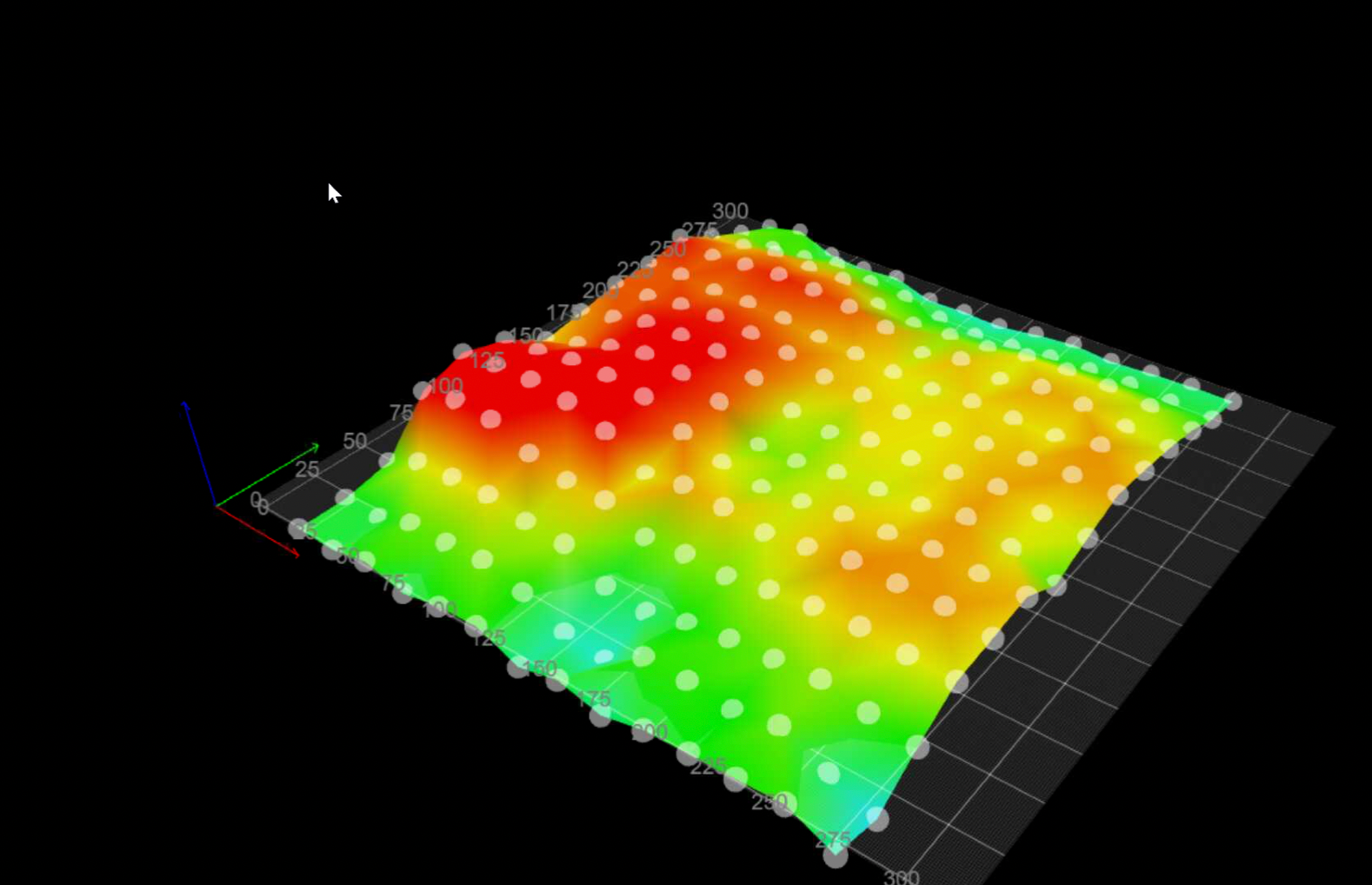
Heat Map:
Config Files:
download.zipStart gCode:
; Railcore 300ZL start code - 20 May 2021
M140 S[first_layer_bed_temperature] ; Raise bed temp to profile requested bed temp
M190 S[first_layer_bed_temperature] ; Wait for bed temp to rise
G28 ; home all axes
G32 ; Autocalibrate bed
G32 ; Autocalibrate bed a second time
G28 Z ; Home Z after bed leveling
G29 S1 ; Apply mesh bed leveling
;
G1 Z20 F600 ; Move bed down 20
M104 S[first_layer_temperature] T0 ; Raise hot-end temp to profile requested hot-end layer 1 temp
M109 S[first_layer_temperature] T0 ; Wait for hot-end temp to rise to profile requested hot-end layer 1 temp
;
G1 X0.0 Y0.0 Z1.0 F2000.0 ; prepare to prime
G92 E0 ; reset extrusion distance
G1 Z0.2 F600
G1 X60.0 E9.0 F1000.0 ; priming
G1 X125.0 E12.5 F1000.0 ; priming
G1 Z0.5 F600
G92 E0 ; reset extrusion distance
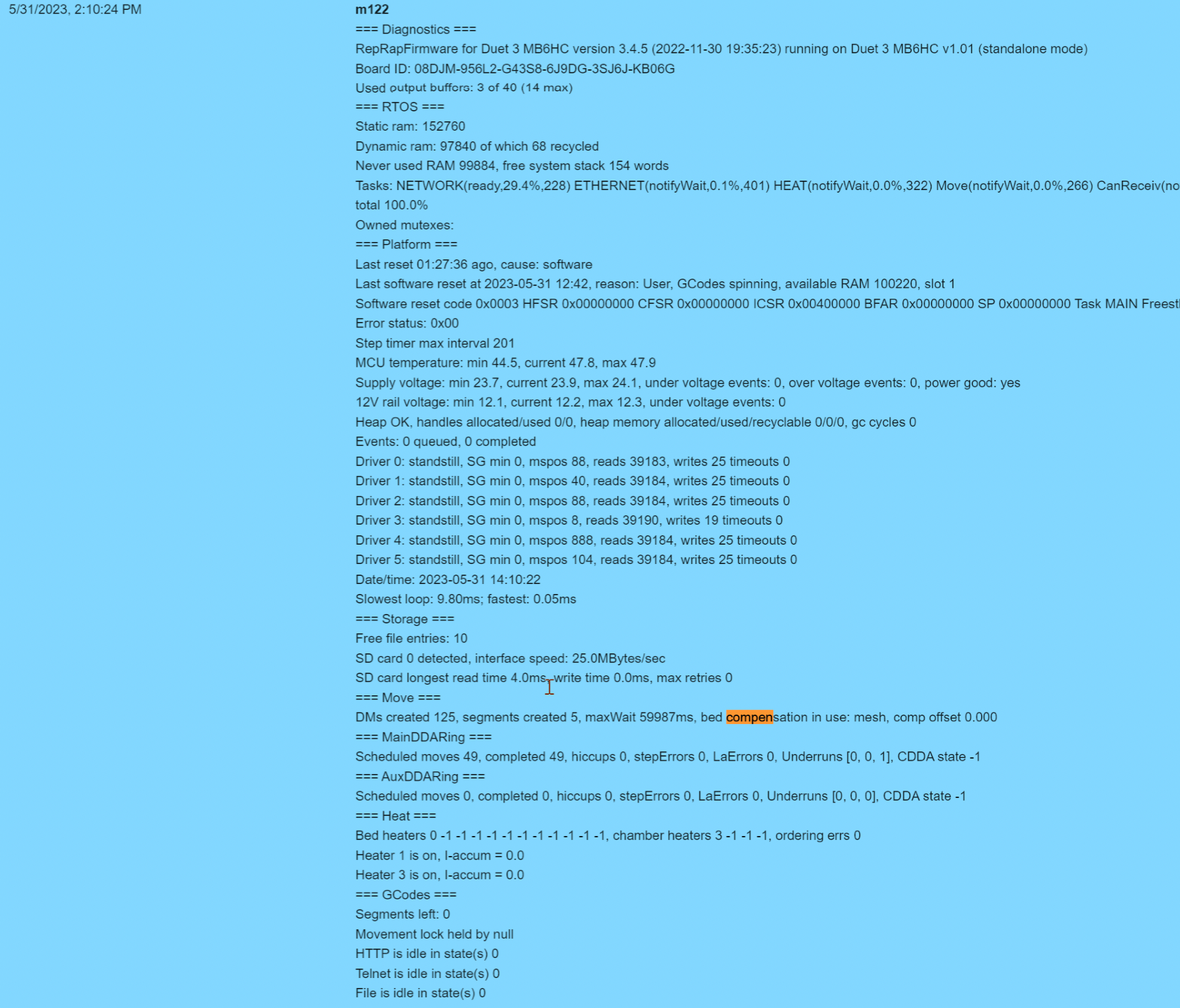
; end of start codeM122:
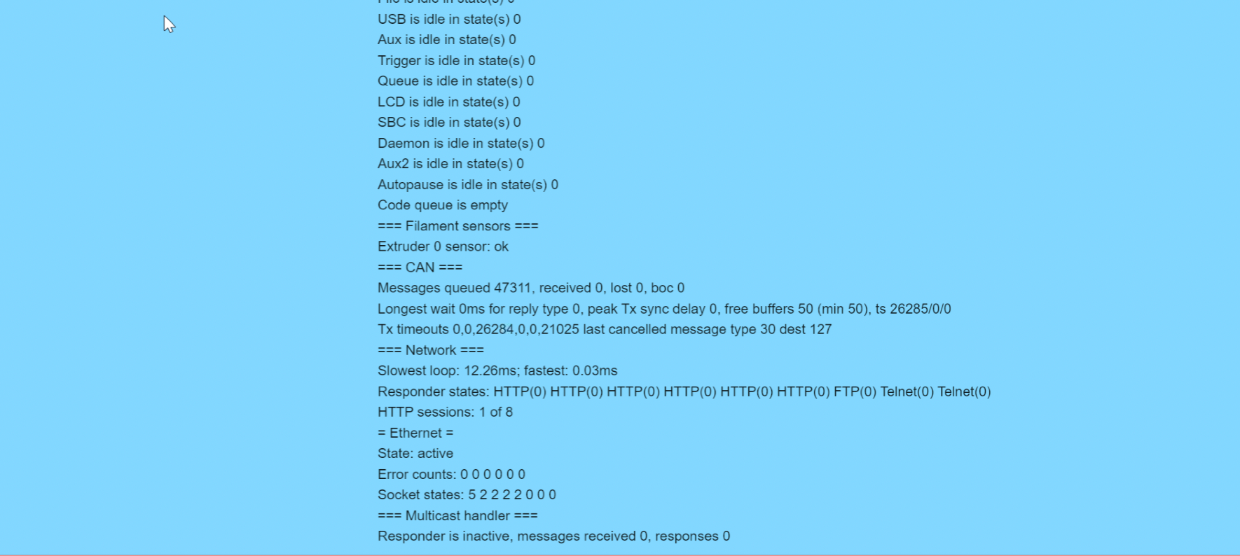
M98 P"config.g":

-
Mesh Bed Leveling expected behaviorposted in General Discussion
Hi.
My machine has started misbehaving, and I'm struggling to get good first layers. According to the height map I've generated, there are some low spots and some high spots in my bed.
I've run G29 S1 to load that map at the beginning of a job, but it doesn't seem like the printer is doing any actual compensation, as I get poor adhesion in the low spots and squeegeed out filament in the highs. (Is there anything else I'm supposed to do to get compensation?)
Anyway, trying to simplify the debugging I moved between a few points on the plate did a G0z0.51 (equivalent to a 0.020" feeler gauge). I'm not getting consistent gaps between the nozzle and the bed.
Should the map be applied to a random move like that outside a formal "print"? I would assume so, but we're in uncharted territory here for me.
Assuming it should, then something's not working right. Any ideas?
Thanks
-Ben -
RE: DWC Progress Questionposted in Duet Web Control
Heh, I guess so. Weird. I thought I updated everything correctly when I set this up a week ago, but I guess the DWC is still ancient.
Stand by...
-
RE: DWC Progress Questionposted in Duet Web Control
DWC 2.1.0
Board: Duet 3 MB6HC (MB6HC)
Firmware: RepRapFirmware for Duet 3 MB6HC 3.1.1 (2020-05-19b2)File:
https://www.dropbox.com/s/xfxyj7xei4st8up/Rebuild BLTouch Radius_0.1mm_PLA_.gcode?dl=0 -
DWC Progress Questionposted in Duet Web Control
Question about the progress displays.
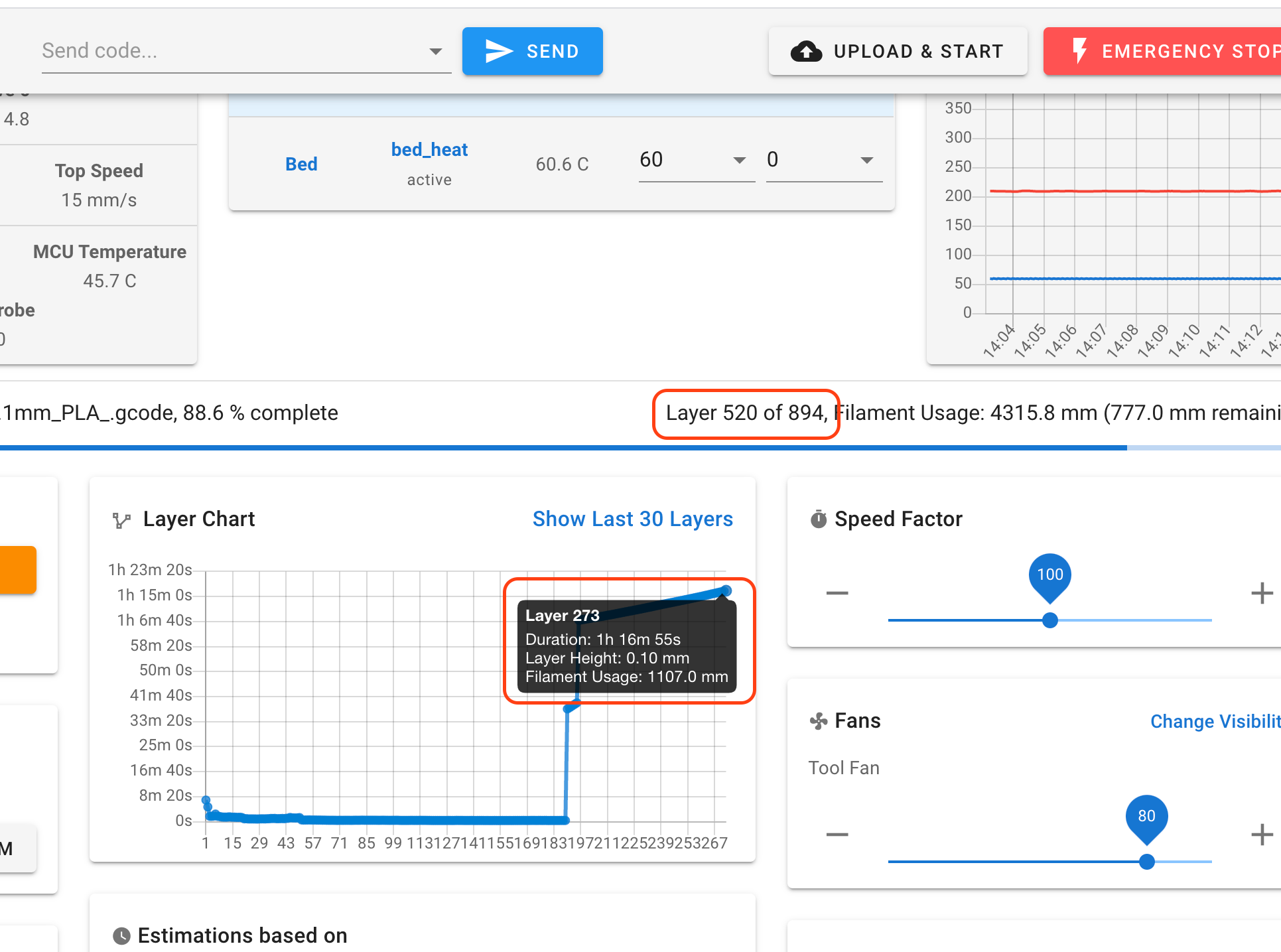
In the attached screenshot, the red boxes highlight what seems to be a bug. The layer count shows we're at 520 of 894, but the Layer Chart is only updated through Layer 273. Any thoughts on why that might be and/or if it really is a bug?
-Ben
-
Bed Mesh <> Orthogonal Axis Compposted in Duet Hardware and wiring
Howdy!
Quick question for the experts. If I'm using M556 to tune out the last bit of axis error, when and how does this affect the global coordinate space of the printer?
Particularly, I'm wondering if I need to do things in a particular order so that a probed bed mesh registers properly to the compensated coordinate space?
I realize this should be a pretty insignificant factor given the relatively minor adjustments that the M556 are going to make and the coarse probing grids used for mesh compensation, but I find understanding little things like this create great insight into how a system works

Thanks,
-Ben -
RE: Duet 3 2-Wire Fan Helpposted in Duet Hardware and wiring
Fair enough...
After reading this:

And looking at this:
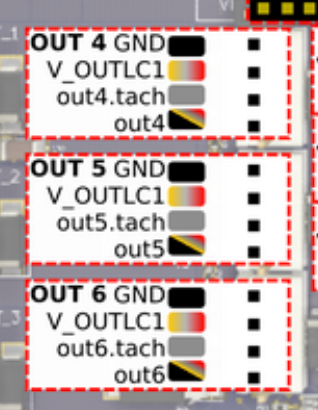
I had to figure out where to connect the wires.
For the positive leg, V_OULCn clearly maps to the V_OUTLC1 pins in the picture. That said there's a typo. The doc should read V_OUTLCn not V_OULCn.
I was confused about the ground leg. The text "OUT_n_NEG pin (-ve)" from the doc doesn't map to specific text in the drawing. The closest looking one is OUT 6 GND so I went with that. If the doc read that it should go to outn it would be clearer.
-
RE: Duet 3 2-Wire Fan Helpposted in Duet Hardware and wiring
@bearer Ah HA!
If someone who edits the docs is watching, I found the description to be super confusing...
-
Duet 3 2-Wire Fan Helpposted in Duet Hardware and wiring
Hello!
I'm trying to get my fans (hot end and layer) working for my new build and can't figure it out. This is for a Duet3 so the docs still seem a bit thin.
They're both 2 wire fans, connected to the top two pins of OUT4 and OUT5. (GND and V_OUTLC1) This is what I understood to be correct from the following instructions on the Duet3 Wiring Guide:
4-pin KK connectors with offset spigot OUT_4 thru OUT_6: these are intended for PWM-controllable fans. The connector fits a standard PC-type 4-pin PWM fan. Alternatively, a 2-pin fan may be connected between the V_OULCn pin (+ve) and the OUT_n_NEG pin (-ve).
The fans come on, but they're always at 100% and I can't get them to turn off or modulate the speed at all.
Any thoughts?
Here's my config:
; Fans
M950 F0 C"out5" ;Hotend fan on "out5" connector
M106 P0 S255 H1 T50 ;enable thermostatic mode for hotend fan
M950 F1 C"out4" ;Layer fan on "out4" connector
M106 P1 S0 ;Layer Fan -
RE: Probe Helpposted in Duet Hardware and wiring
@Phaedrux Ok. I'll look around. I've googled a bunch and I'm having a hard time figuring out the difference between P5 and P8. Filtered vs. Unfiltered isn't a distinction I understand intuitively, and that's the extent of the distinction in the docs I've found. How are these functionally different?
-
RE: Probe Helpposted in Duet Hardware and wiring
Interesting. I was focusing on the config instructions from PrecisionPiezo which indicate that one should use Type1 for an analog setup, so I'm not sure quite what to read into that. The board has both an analog and a digital output...
-
RE: Probe Helpposted in Duet Hardware and wiring
Well, I got it working. I had to convert from the analog probe type to digital, but now it's all good.
Not at all sure why it wasn't working in analog mode, but whatever.
-
RE: Probe Helpposted in Duet Hardware and wiring
Sorry for the delayed reply. Here's the relevant portion of the M112 output:
=== Diagnostics ===
RepRapFirmware for Duet 3 MB6HC version 3.1.1 running on Duet 3 MB6HC v1.01 or later (standalone mode)
Board ID: 08DJM-956L2-G43S8-6J9DG-3SJ6J-KB06GI updated the M558 line and I'm getting the same error. Sigh...

-
Probe Helpposted in Duet Hardware and wiring
Hello! I'm grinding my way through setup and config for the first time. I've got X and Y dialed in, but I can't figure out what I'm doing wrong with my z probe. I'm using a piezo20 module. The config.g and homez.g files are below.
Whenever I run a homing routine for Z I get:
Error: in file macro line 5: G30: Z probe 0 not found
Error: G0/G1: insufficient axes homed.Any thoughts on what's going on here?
Thanks!
-Benhomez.g:
G91
G1 Z5 F800 H2 ;RRF3 change S2 to H2
G90
G1 X150 Y150 F2400
G30
G1 Z2 F200config.g:
; Enable network
M552 P0.0.0.0 S1;General Setup - RailCore RRF on a SBC for Duet3
G21 ;Work in millimetres
G90 ;Send absolute coordinates...
M83 ;...but relative extruder moves; Stepper configuration
M569 P0 S1 D3 ;Drive 0 Z Rear Left
M569 P1 S1 D3 ;Drive 1 Z Front Left
M569 P2 S1 D3 ;Drive 2 Z Right
M569 P3 S1 D3 ;Drive 3 Extruder
M569 P4 S1 D3 ;Drive 4 X / Rear
M569 P5 S0 D3 ;Drive 5 Y / Front;Axis configuration
M669 K1 ;corexy mode
M584 X4 Y5 Z1:0:2 E3 ; Map X to drive 0 Y to drive 1, Z to drives 2, 3, 4, and E to drive 5;Leadscrew locations
M671 X-10:-10:333 Y22.5:277.5:150 S7.5M350 X16 Y16 Z16 E16 I1 ;set 16x microstepping for axes with interpolation
M906 X1400 Y1400 Z1200 E800 I80 ;Set motor currents (mA)
M201 X2500 Y2500 Z100 E1500 ;Accelerations (mm/s^2)
M203 X24000 Y24000 Z900 E3600 ;Maximum speeds (mm/min)
M566 X800 Y800 Z100 E1500 ;Maximum jerk speeds mm/minute
M208 X290 Y290 Z280 ;set axis maxima and high homing switch positions (adjust to suit your machine)
M208 X0 Y0 Z0 S1 ;set axis minima and low homing switch positions (adjust to make X=0 and Y=0 the edges of the bed)
M92 X200 Y200 Z1600 E837 ;steps/mm; End Stops
M574 X1 S1 P"io2.in" ;Map the X endstop to io2.in
M574 Y1 S1 P"io1.in" ;May the Y endstop to io1.in; Thermistors
M308 S0 P"temp0" Y"thermistor" A"bed_heat" T100000 B4240 H0 L0 ;Bed thermistor - connected to temp0
M308 S1 P"temp1" Y"thermistor" A"e0_heat" T100000 B4725 C7.06e-8 H0 L0 ;duet3 e3d thermistor - connected to e0_heat;Define Heaters
M950 H0 C"out0" T0 ;Bed heater is on out0
M950 H1 C"out1" T1 ;Hotend heater is on out1;Define Bed
M140 H0M307 H0 A90.0 C700.0 D10.0 S1.00 B1 ;Keenovo duet 3 configuration
M307 H1 A310.1 C144.7 D2.6 S1.00 B0 ;E3D Hotend duet 3 configurationM570 S360 ;Hot end may be a little slow to heat up so allow it 180 seconds
M143 S285 ;Set max hotend temperature; Fans
M950 F0 C"out5" ;Hotend fan on "out5" connector
M106 P0 S255 H1 T50 ;enable thermostatic mode for hotend fan
M950 F1 C"out4" ;Layer fan on "out4" connector
M106 P1 S0 ;Layer Fan; Tool definitions
M563 P0 D0 H1 F1 ;Define tool 0
G10 P0 S0 R0 ;Set tool 0 operating and standby temperatures;Piezo Probe
M558 P1 C"io0.in" I0 R0.4 F300 X0 Y0 Z0
G31 X0 Y0 Z-0.1 P600T0 ;select first hot end