@jay_s_uk I'll retry it, thanks 
Best posts made by Aodrennn
Latest posts made by Aodrennn
-
RE: M955: Accelerometer not found on specified portposted in Using Duet Controllers
@jay_s_uk
Thanks, I'll remake the wiring with very shorter cables.
I tried yesterday with a USB3 cable but nothing better, do you think the LIS3DH is possibly broken ? -
RE: M955: Accelerometer not found on specified portposted in Using Duet Controllers
@cosmowave
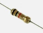
So I just put a resistor like this on the CS pin on the LIS3DH and it would works ?
 -
RE: M955: Accelerometer not found on specified portposted in Using Duet Controllers
@jay_s_uk
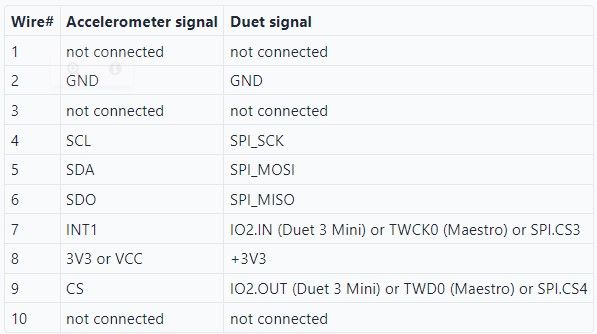
Yeah I just followed this picture on this page : https://duet3d.dozuki.com/Wiki/Accelerometers
-
RE: M955: Accelerometer not found on specified portposted in Using Duet Controllers
@phaedrux
I reduced the cable and it's like this now :
I also tested all cables with a multimeter and there are all good ...I'll think I'll test with an USB 3 as you said.
-
M955: Accelerometer not found on specified portposted in Using Duet Controllers
Hello,
I use Duet 3 mini 5+ running RRF 3.4.1 and I want to add an accelerometer to use imput shaping and reduce ghosting.
I have wired up some cables and connected them to IO4 (input and output) and the temperature daughter board (as I saw on the Duet Dozuki documentation).
When the cables are connected, I can see a green led on the accelerometer but when I send "G1 X-50 G4 S2 M956 P0 S1000 A0 G4 P10 G1 X50 F20000" the console tell me that no accelerometer is connected.
Obviously, I've got the "M955 P0 S1344 R10 C"io4.out+io4.in" Q2000000" on my config.g and if I send this in the console, I've got the same answer :"Accelerometer not found on specified port".
I saw that someone added a resistor and it works then, why ?
Should I do the same thing ?
Thanks


-
RE: Bed mesh compensation don't compenses all deviationsposted in Using Duet Controllers
@phaedrux
I'll test that, thanks ! -
Bed mesh compensation don't compenses all deviationsposted in Using Duet Controllers
Hi,
I've got problems with compensation on my first layers.
When I probe (G29), I measure a deviation between 2 points of 0.4mm, however, when I print a straight line between these 2 points, I measure a compensation on the Z motors of only 0.2mm.
Is there a maximum compensation value? Or a factor to change in the config.g?
My printer is a Ratrig VCore 3, I use RRF3 on a Duet3 mini 5+ and here is my config.g :
; General preferences
G90                                     ; send absolute coordinates...
M83                                     ; ...but relative extruder moves
M550 P"GigaRat"                        ; set printer name
M669 K1                                 ; CoreXY
G21                                  ; Set Units to Millimeters

; Network
M552 S1                        ; enable network and acquire dynamic address via DHCP
M586 P0 S1                              ; enable HTTP
M586 P1 S0                              ; disable FTP
M586 P2 S0                              ; disable Telnet

; Drives
M569 P0.0 S1 D2                         ; physical drive 0.0 goes forwards
M569 P0.1 S1 D2                         ; physical drive 0.1 goes forwards
M569 P0.2 S1 D2                         ; physical drive 0.2 goes forwards
M569 P0.3 S1 D2                         ; physical drive 0.3 goes forwards
M569 P0.4 S1 D2                         ; physical drive 0.4 goes forwards
M569 P0.5 S1 D2                         ; physical drive 0.5 goes forwards
M584 X0.5 Y0.4 Z0.0:0.1:0.2 E0.3        ; set drive mapping
M350 X16 Y16 Z16 E16 I1                 ; configure microstepping with interpolation

M92 X80.154 Y80.154 Z798.56               ; set steps per mm
M906 X1300 Y1300 Z1000 I30               ; set motor currents (mA) and motor idle factor in per cent
M84 S10                                 ; Set idle timeout

M566 X400.00 Y400.00 Z6.00 E120.00 P1          ; set maximum instantaneous speed changes (mm/min)
M203 X10800.00 Y10800.00 Z1000.00 E3600.00     ; set maximum speeds (mm/min)
M201 X3000.00 Y3000.00 Z100.00 E3600.00        ; set accelerations (mm/s^2)

; Axis Limits
M208 X0 Y0 Z0 S1                               ; set axis minima
M208 X286 Y280 Z280 S0                         ; set axis maxima

; Endstops
M574 X1 S1 P"io1.in"                           ; configure active high endstops
M574 Y2 S1 P"io3.in"                           ; configure active high endstops
M574 Z1 S2                                     ; configure Z-probe endstop for low end on Z

M671 X-4.5:150:304.5 Y-4.52:305:-4.52 S5       ; define positions of Z leadscrews or bed levelling screws
M557 X30:286 Y0:225 P5                        ; define 5x5 mesh grid
M376 H20

; Heaters
M308 S0 P"temp0" Y"thermistor" T100000 B3950 A"Bed"    ; configure sensor 0 as thermistor on pin temp0
M950 H0 C"out0" T0                                     ; create bed heater output on out5 and map it to sensor 0
M307 H0 B0 S1.00                                       ; disable bang-bang mode for the bed heater and set PWM limit
M140 H0                                                ; map heated bed to heater 0
M143 H0 S121                                           ; set temperature limit for heater 0 to 110C

;; Run Bed PID Tune!! Bellow is an example for a 300x300 bed
M307 H0 A303.1 C356.7 D1.4 S1.00 V24.0 B0

; Fans
M950 F0 C"out6" Q500                   ; create fan 0 on pin out3 and set its frequency
M106 P0 C"Hotend Fan" S0 H1 T45 L255   ; set fan 0 name and value. Thermostatic control turned on for Hotend
M950 F1 C"out4" Q500                   ; create fan 1 on pin out4 and set its frequency
M106 P1 C"Layer Fan" S0 H-1 L255       ; set fan 1 name and value. Thermostatic control is turned off

M308 S10 Y"mcu-temp" A"MCU"                        ; MCU temp on temp sensor 10
M950 F2 C"out3"                                    ; create fan 1 on pin out6 and set its frequency
M106 P2 S255 H10 T20                               ; set fan 1 value. Virtual thermostatic control is turned on, turn on and off
M912 P2 S0                                     ; MCU temperature calibration

; Tools
M563 P0 D0 H1 F1           ; define tool 0
G10 P0 X0 Y0 Z0            ; set tool 0 axis offsets
G10 P0 R0 S0               ; set initial tool 0 active and standby temperatures to 0C

M950 H1 C"out1" T1         ; create nozzle heater output on out2 and map it to sensor 1
M307 H1 B0 S1.00           ; disable bang-bang mode for heater and set PWM limit
M143 H1 S280               ; set the maximum temperature in C for heater

; EVA 2 / BMG / E3D V6

M92 E409          ; set extruder steps per mm, 0.9 angle/step (LDO Pancake)
M906 E800         ; set extruder motor current (mA) and idle factor in per cent

M308 S1 P"temp1" Y"thermistor" T100000 B4725 C7.060000e-8 A"Hotend"
;; Run Heater PID Tune!!
M307 H1 A751.5 C196.6 D4.7 S1.00 V23.9 B0

; Z-Probe
;; Inductive Probe
; M558 P5 C"!io3.in" H5 F400 T5000       ; set Z probe type to unmodulated and the dive height + speeds
; G31 P500 X-30 Y-15 Z0.20               ; set Z probe trigger value, offset and trigger height, more Z means closer to the bed
;; BLTouch
M950 S0 C"io2.out"                     ; Create a servo pin on io7
M558 P9 C"io2.in" H5 F240 T10800 A5    ; set Z probe type to unmodulated and the dive height + speeds
G31 P25 X24.5 Y-46 Z3.5          ; set Z probe trigger value, offset and trigger height, more Z means closer to the bed


; Pressure Advance
M572 D0 S0.035

; PanelDue
M575 P1 S1 B57600

;Température Chambre
M308 S2 P"temp2" Y"thermistor" T100000 B4725 A"Chambre"
;M950 F2 C"out5" T2                  ; create fan 0 on pin out3 and set its frequency
;M106 P2 T40:60 H2   ; set fan 0 name and value. Thermostatic control turned on for Hotend

T0
Thanks ;))
-
RE: Weak torque only during head travelposted in General Discussion
@deckingman
Yeah I think I'll use MCU temperature to control the fan.
Thanks for all it gaves me ideas and orders of magnitudes. -
RE: Weak torque only during head travelposted in General Discussion
@deckingman
The motherboard is outside the printer chamber so I think it's okay. But it cost nothing to put a fan on the motherboard so I think I'll do that. -
RE: Weak torque only during head travelposted in General Discussion
@deckingman
In fact, I never changed that point in the config.g lol, thank you for pointing this out to me.Thanks for all informations ;))