@Frederik
Add an M291 between the M409 and the if statement. I have updated the macro below with this
M291 P{move.calibration.initial.deviation} S3
Based upon these values
M208 X0 Y0 Z0 S1                 ; set axis minima
M208 X415 Y395 Z400 S0           ; set axis maxima
G10 P0 X0 Y0 Z0                  ; set tool 0 axis offsets
the nozzle should be considered at x0 y0 and the BLTouch at x-38 y-10 in the comment below.
when my printhead is homed at x0 y0 (left front corner) the bltouch is around x-3 y-2
the nozzle x35 y8
This
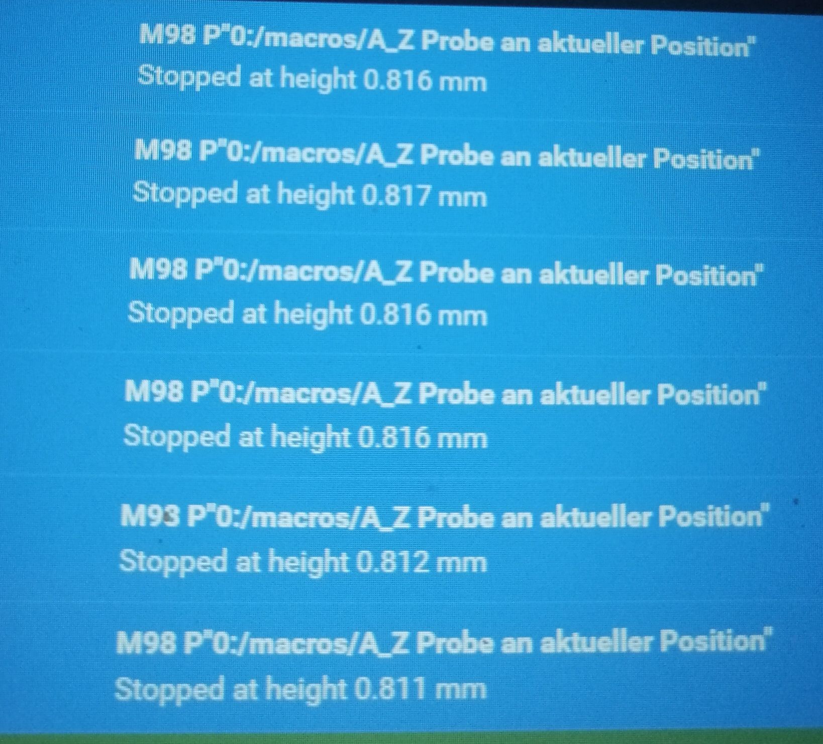
G31 P1000 X0 Y0 Z0.81 ; BLTouch offset
should be updated to this
G31 P1000 X-38 Y-10 Z0.81 ; BLTouch offset

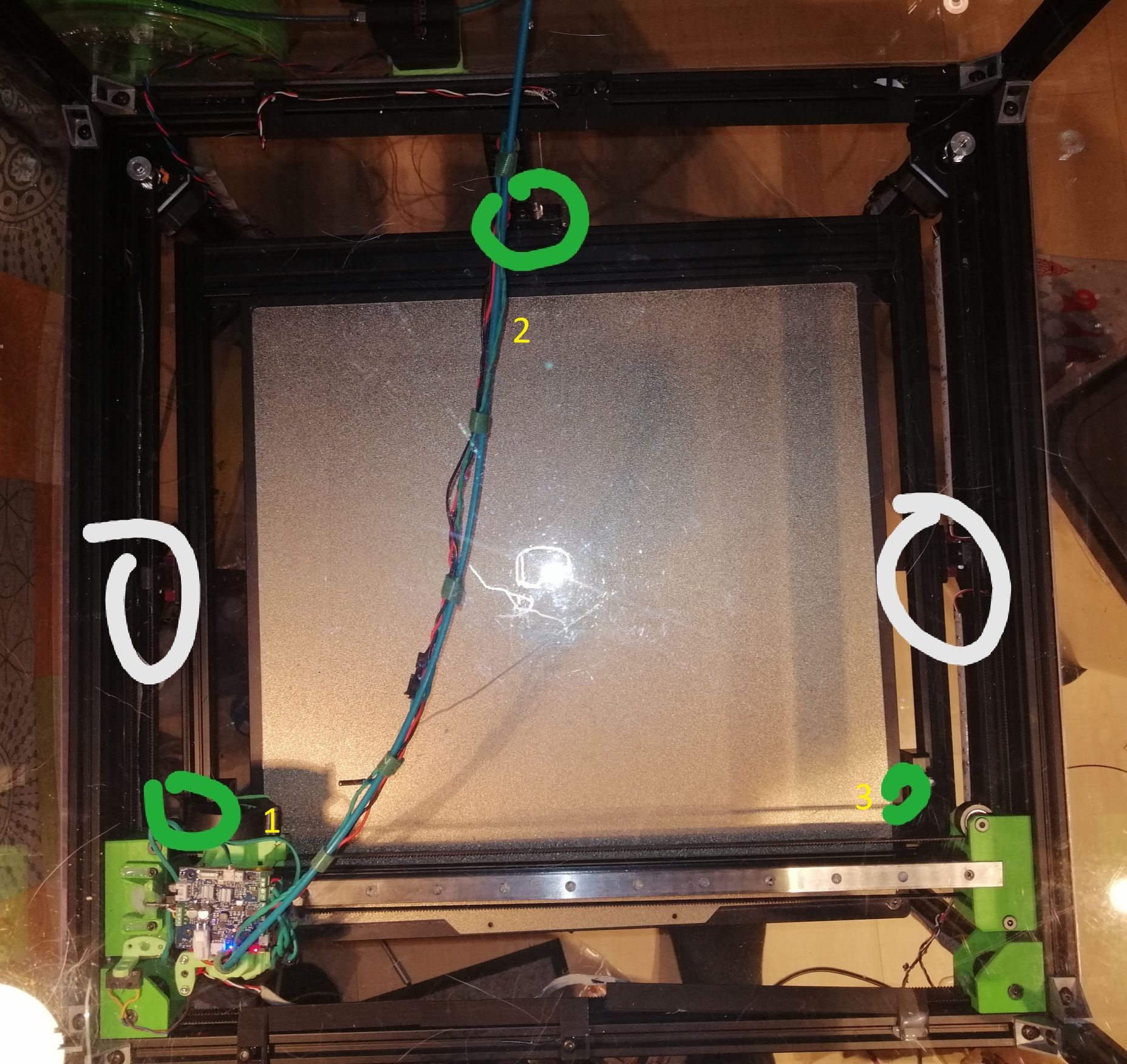
For M671 move the tool head to the position indicated by the (1) of x0 y(align the nozzle to the spindle). Measure from the center of the nozzle to the center of the spindle and subtract that number from x0. The Y value will be the Y position as indicated by the DWC tool position.
Next move tool head to position 2 of x(align the nozzle to the spindle) y395. Measure from the center of the nozzle to the center of the spindle and add that number to y395. The X value will be the X position as indicated by the DWC tool position.
Next move tool head to position 3 of x415 y(align the nozzle to the spindle). Measure from the center of the nozzle to the center of the spindle and add that number to x415. The Y value will be the Y position as indicated by the DWC tool position.
Update the M671 with the values collected from the above steps.
M671 X0:215:450 Y80:450:80 S5 ; Position of Leadscrews
Next copy your first G30 command from the 3point calibration
G30 P0 X40 Y80 Z-99999
to the console and send it the printer. Once the command has finished record the tool position as indicated by the DWC. Use this x and y value in a G1 x## y## command at the beginning of the 3point calibration followed by G30 to set the z height.
Update the 3point calibration macro to something like
M203 Z100 ; set a low z max speed to increase accuracy. Run multiple G30 S-1 to determine the speed needed to achieve the accuracy you need.
G28
while true
        G1 X## Y## ; enter the tool position as indicated by the DWC after running the first G30 command in the 3point calibration
        G30 ; sets the first point of the 3point calibration as Z0
	G30 P0 X40 Y80 Z-99999          ; Probe near the front left lead-screw
        G30 P1 X215 Y395 Z-99999        ; Probe near the rear lead screw
        G30 P2 X415 Y80 Z-99999 S3      ; Probe near the front right lead-screw
	M409 K"move.calibration.initial.deviation" ;displays deviation in console
        M400 ; wait for move to complete
        M291 P{move.calibration.initial.deviation} S3 ;displays deviation value
	if move.calibration.initial.deviation <= 0.001  ; change the 0.001 to your needed value
		echo "Passed"
                M203 Z1000 ; set this z max speed to match your config file. Note if you cancel this macro by selecting the cancel button on the M291 message box this command will not run. You will need to run this command from the console to restore the max z speed
		break
	continue
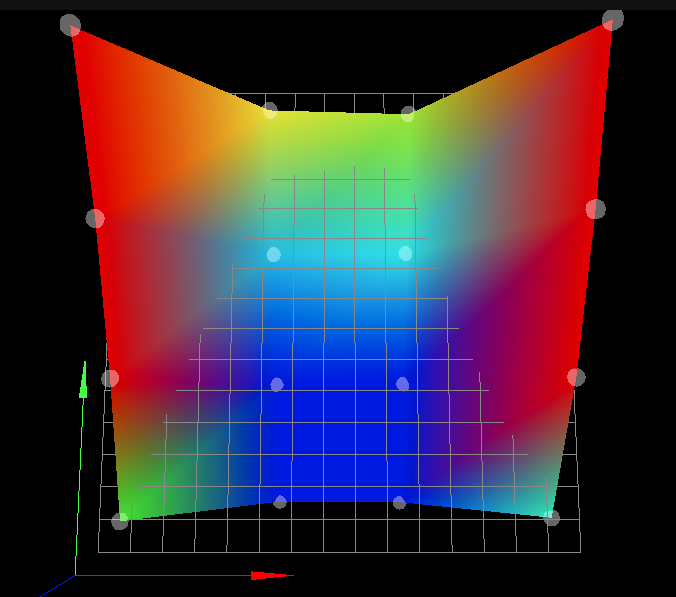
Follows these steps above to double check all your setting are correct. Lets the 3point calibration macro run until the deviation no longer decreases and post the results.
@Phaedrux
This is my understanding of the calibration process for 3 motor Z axis calibration.
If something is not correct please update it. This is the process I used to set mine up and it works perfectly.
Edit: {
Added M203 to start and end of macro to increase probe accuracy.
@3dML said in RRF3.2Beta4.1 Heightmap vs. Spindle/Driver Mapping:
@Frederik
I have found that slowing down the maximum Z speed can help with tolerance.
}
![20210103_165838[1].jpg](/assets/uploads/files/1609714866593-20210103_165838-1.jpg)


