Printed part tolerance too slack
-
I want a cable management tray for my height-adjustable desk.
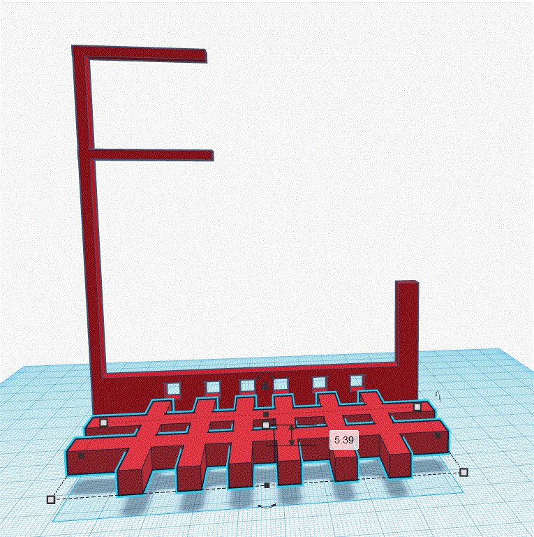
I came up with the following design:
https://www.tinkercad.com/things/aUADCcVNotf?sharecode=Jyw1OSVmBfHwjXB1S7eIqacKr6VmH6MCha-vOcEbDW4It appears to fit nicely in CAD but when printed the parts don't fit nicely. You can use force but it distorts the part. I have already snapped 2 of them.
Any advice will be greatly appreciated. It would have been easier to buy a tray. However, that would have robbed me of the chance to learn more about designing for 3D printing.
Here is an image to show how it distorts the hanger part:
Photo of a 3D printed cable management model that is bent and distorted
As you can see in the image, the hanger part is bent. I have checked the calibration of the printer, it seems fine on both the X and Y-axis. It's 0.2 mm out on the Z-axis
-
@ageis, your image did not post.
When you design a part that is to be 3D printed, you need to introduce enough clearances to account for the manufacturing process (printing). There is no such thing as a perfect anything. Different processes have different tolerances and 3D printing is not a really precise process. -
could you elaborate more on introducing clearance. Right now my models don't turnout out similar to the model.
-
@ageis it might help if you post the photo. Without the photo I can't really comment. You might also want to explain what you mean whaen you say "my models don't turn out similar to the model"
-
So I have found out the resolution of my printer in the x direction is 0.3mm and 0.1mm in the z direction.
I have made the holes 0.3mm bigger in x and z direction .I find the hole is too small for the second part to slot into it.
if that still isn't big enough then I give up. I will remodel it as one big piece.
-
@ageis, 0.3 mm is not excessive. I use that quite frequently. Don't call that a 'resolution' issue though. Your printer might have a much much higher accuracy for positioning the nozzle but there are all kinds of inaccuracies introduced as you lay down the filament (even if your nozzle was to be within 0.001 mm of where it should be). On top of all that, there are errors introduced during the slicing. For example, a hole is never 'round'. It is an approximation of round with many little facets. The net effect is that the hole is always smaller then as laid out in the CAD program (some slicers have a setting to compensate for that)
While round holes is not an issue in your case, you will run into other errors such as bulging corners from inaccurate pressure advance calibration or even things like ripples introduced due to harmonic vibrations as the printer prints.Good luck!
