Unable to stop severe bulging in corners with new print head
-
would you be willing to share your print profiles and gcode for both the benchy and the test specimen with the bulging corners?
The benchy prints completely different than just a rectangular box due to internal and external geometry differences.
My best guess at this misbehavior is high jerk and low acceleration leading to heavy deviation of the print head at corners due to inertia.
-
@Threepwood Have you tried simply increasing the PA value?
-
@Threepwood Also worth doing would be to try your test part as a single wall object with no infill to see if the corners still bulge or not? Are you printing external perimeters first and did you do the same for both the benchy and the test part?
-
@Threepwood .... also, what speed are you printing at? Does the bulging get better/worse/stay the same if you reduce print speed?
-
@Threepwood Can we just check when you printed the benchy in the yellow/green was this using the same settings (in both RRF and the slicer) as when you print the rectangular test item?
-
Hi guys,
Your questions got me thinking. I hadn't tried any other slicers. It didn't seem likely to me that a slicer setting could cause this.
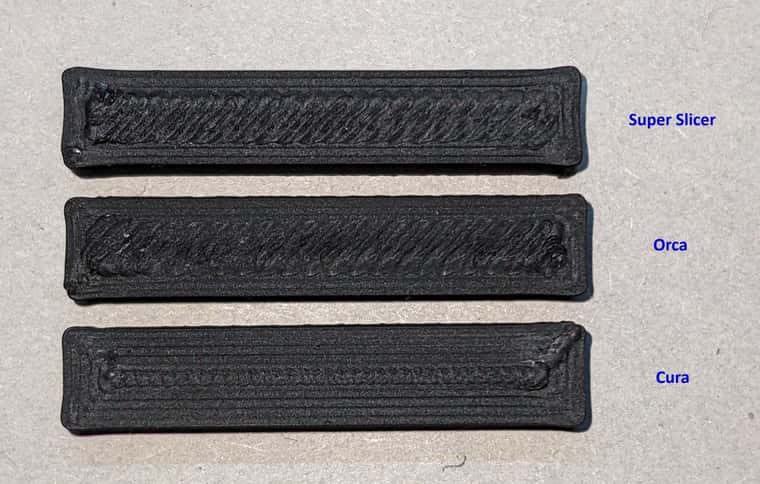
This is the result of dropping the model into Orca and Cura.

I'm finally on to something! The Orca settings are pretty much a mirror of the SuperSlicer settings with speeds and accelerations and jerk. The corners are still not perfect, but what a difference! I can probably tune out the tiny bulge in Orca or Cura by slightly increasing PA value further.
I have now also tried using Vez3D's SuperSlicer config, which changes all settings in "Print settings" "Filament settings" and "Printer settings". But I still get bulging in SuperSlicer. So it seems as if the problem isn't a setting in SuperSlicer, but in how SuperSlicer is working with my printer and firmware. I ran a search for M572 to check it wasn't changing the PA value, and it returned no M572 found.
-
@Threepwood can you post the model here you are testing? I have a goliath hotend so i can repeat the test on my machine (only difference is a use an orbiter v2).
What nozzle size are you using? -
@jay_s_uk Here is the stl. I'm using a 0.5mm CHT nozzle.
-
 undefined Threepwood has marked this topic as solved
-
Small update. I've re-run my pressure advance tests and the results at both 255°C and 270°C are around 0.08 this time. When I ran the pattern and tower tests just after installing the new hotend and got 0.02 to 0.025.
Now importantly, I have just switched from a CHT 0.5mm to a CHT 0.4mm, so I would expect an increase, but the difference is huge. I suspect that before I moved to the 0.4mm nozzle, my ideal PA vaule was actually a lot higher than the 0.02 that I had originally set it to, due to the multiple tests I ran, which showed 0.02 to be a reasonable value. I later found that the offcial VZbot firmware has PA set to 0.02.
I have no idea why the PA value has increased so much. What kind of difference should we expect to see between a 0.5mm and 0.4mm nozzle? I wonder if there was some clogging in the old nozzle, but I'm not sure that the new 0.4mm should be so high.
-
@Threepwood said in Unable to stop severe bulging in corners with new print head:
...............What kind of difference should we expect to see between a 0.5mm and 0.4mm nozzle? I wonder if there was some clogging in the old nozzle, but I'm not sure that the new 0.4mm should be so high.
The area of a 0.4mm diameter nozzle is about 0.126 mm^2. The area of a 0.5mm nozzle is about 0.196 mm^2. So although the difference in diameter is only around 20%, the difference in area is around 60%. So 60% more restriction to flow equals a hell of a lot more of a pressure build up behind the nozzle and it doesn't surprise me in the slightest that you need much more PA to compensate with the smaller nozzle.
I don't know what method you use to find the PA value but it was clearly too low. I also don't understand why "the official VZbot firmware" only states a single value when there are so many parameters which can affect pressure build up in the hot end - not least of which is nozzle diameter closely followed by the viscosity of the filament which in turn can be greatly affected by the temperature one uses.
By way of some additional data points, I'm currently running a Bondtech LGX Ace close coupled to a Slice Engineering Mosquito. This has a small melt chamber and the shortest filament path between the extruder outlet and the hot end inlet known to mankind. With a CHT 0.5 mm nozzle, the PA settings I've established after extensive testing are 0.03 for ABS and ASA at around 255 deg C, 0.04 for PLA at 185 deg C, 0.06 for PET-G and Tglass at around 230 deg C.
-
@deckingman When I first tested it with the 0.5mm nozzle, it wasn't too low. But perhaps I had a slight blockage, which increased back pressure. When I took the nozzle out, I could still see old black ABS at the entrance to the nozzle, with the last used white ABS in the middle. Another thing I found was that over time my extruder tension had loosened a little and filament was able to slip before the motor skipped.
With a VZbot build, I think it is assumed that a 0.5mm CHT/Bozzle nozzle is used with ABS. It's just a starting point and anyone going to the lengths of building a VZbot is likely to know that they should calibrate this value. My only point in mentioning it was that it certainly isn't an unreasonable value for PA.
Unfortunately after a lot more testing, and a new nozzle. I'm still getting obvious bulging in corners, which makes a lot of practical parts unusable due to fitment issues. I can start to counter it by using 10,000 accelleration for all print moves and at very, very high PA values like 0.12, but then I get huge underextruded areas before the corner and overextrusion after the corner.
I'm back at the idea that we need a "PA smoothing" value in RRF.

-
@Threepwood said in Unable to stop severe bulging in corners with new print head:
............Unfortunately after a lot more testing, and a new nozzle. I'm still getting obvious bulging in corners, which makes a lot of practical parts unusable due to fitment issues. I can start to counter it by using 10,000 accelleration for all print moves and at very, very high PA values like 0.12, but then I get huge underextruded areas before the corner and overextrusion after the corner.
I'm back at the idea that we need a "PA smoothing" value in RRF.
Personally I think it's back to the laws of physics that I spoke about in your other thread but which you are in denial of. The maker of the video you posted as evidence of that denial did himself state that the model was carefully selected for high speed/high acceleration testing, as was the layer height and other factors (like every corner being rounded). You might be able to accelerate the print head at 10,000 but the filament flow through the nozzle won't accelerate at that rate and PA can only do so much to compensate.
I can get perfectly square corners and make parts that fit together without any issues using an 0.5mm CHT nozzle and without "PA smoothing", but further discussion is pointless and I have nothing more to add.
-
@deckingman Fair enough if you don't want to talk about it anymore. Thank you for your guidence in my troubleshooting threads. It is your right to deny that it is possible to print well, above 4000 accelleration so I won't try to change your mind. What works for you, works for you.
I have tried printing much slower, down to 1000 acceleration with no improvement. At 10k I actually get LESS bulging.
In regards to the bulging in corners @dc42 said this is this thread: https://forum.duet3d.com/topic/28981/issues-with-pressure-advance-since-rrf-3-4
@dc42 said in Issues with pressure advance since RRF 3.4:
PA doesn't fully address the problem of over-extrusion in corners. I am looking to address this separately.
That thread shows that I'm not alone with this problem.
-
I have the same issue on ToolChanger machine too. I haven't found out the root cause yet.
-
 undefined hestiahuang referenced this topic