[Solved][Delta] Precision Piezo issues
-
Hi everyone,
The past two weeks I've dedicated to finishing my Delta build running RRF, and using Precision Piezo piezo's under the bed for probing. I'm using the universal v2.85 board:
https://www.precisionpiezo.co.uk/product-page/universal-piezo-z-probe-pcb-v2-x-for-1-2-3-or-more-piezosI've been using this setup for a long time and it used to work well before. I've noticed that my old setup could be improved a bit as during probing I found the nozzle still pushed quite hard into the bed so I started tweaking the system and found out my issues work somewhat counter-intuitive.
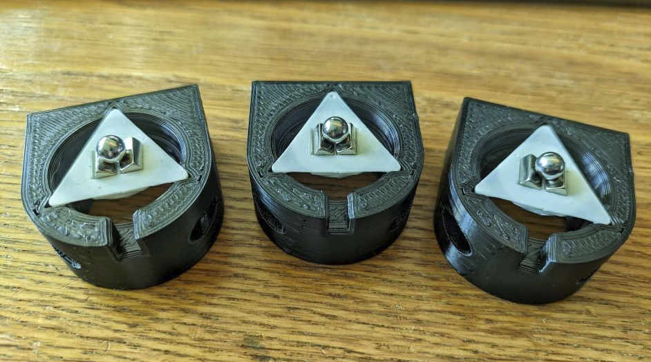
First I raised the plunge speed which seemed to help get a harder hit which triggered better. Then I discovered that the screws that held my bed would change in tightness depending on if the bed was heated or not so I redesigned the whole bed mount system to use a three-point coupling system:

The bed has mounts that connect to the ball magnets and the white triangles have a pointy bottom that pushes in the piezo discs. If the bed heats up, the balls can move outwards, sliding over the block magnets, this makes sure the bed can freely expand while keeping the bed in place.
This is the most sensitive system I've been able to build so far, it literally triggers from the lightest taps (see https://www.youtube.com/watch?v=QssthZMF7tU). I've also been able to probe with it quite well, but still somehow the hotend pushes the bed in, making it deflect between 0.5 and 1 mm.
M558 P5 R0 C"!probe" H2 F7200 T7200 B1
G31 P100 X0 Y0 Z-0.266 S0
These settings seemed to work okay, but a lot of the time I now can't get the probe to get a good enough minimum deviation to start a print.
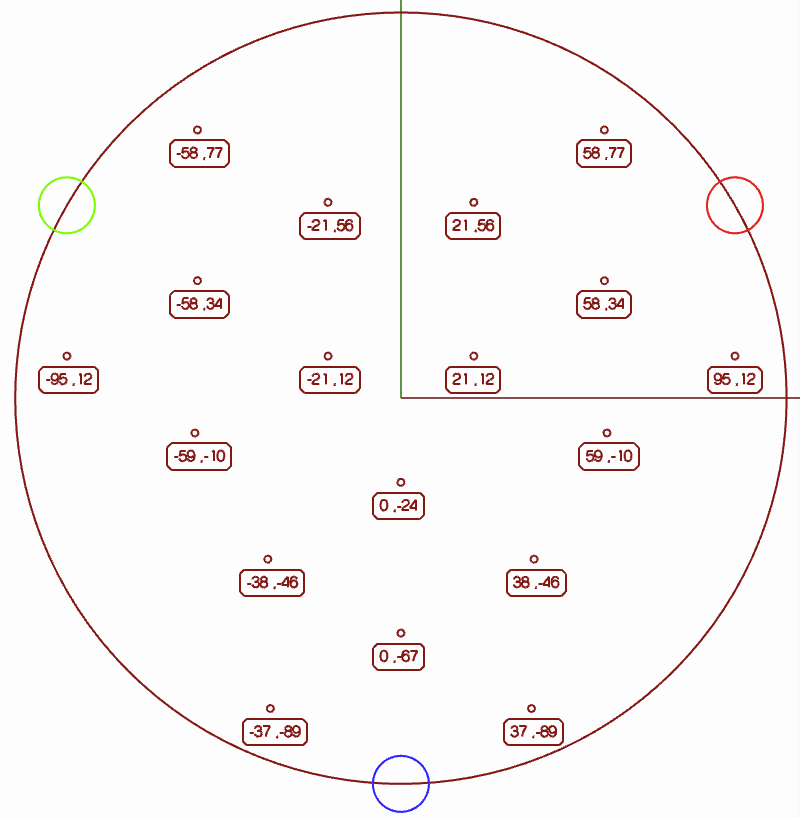
I am using the iterative probing script to probe the bed in the most sensitive areas possible to get the best readings. I designed a program that auto-generates points in places where the piezo probes get the strongest signal (working demo here) :

It ran alright, this is a reasonably working probing example:
https://www.youtube.com/shorts/eEXjATJ_640Still, I couldn't get it to work as good as before. It used to be really gentle and precise, but my old machine used plastic vertexes, had delta rods with lots of play, etc. My new machine has alu vertexes, thick extrusions, precision rods, better bed mounts, etc etc. What could be the problem?
So I did some more reading, when I found this quote from a user over in the piezo probe discussion:
@BlueDust said in Precision Piezo z probes guide for duet users reference:@en_passant
Try swapping the wires from the Piezo Sensor to the Piezo motherboard.If the Piezo triggers on press, its correct, but if it triggers on release try swapping the sensor wires and see if that fixes it.
I did a check, and indeed, the piezo didn't register anything if I pushed in my bed gently and only triggered upon release. So I did what seemed logical and reversed the wires from each piezo disc. This resulted in a direct trigger whenever the bed was pushed in, and the system seemed even more sensitive than before.
I also tried lowering the probe speed to:
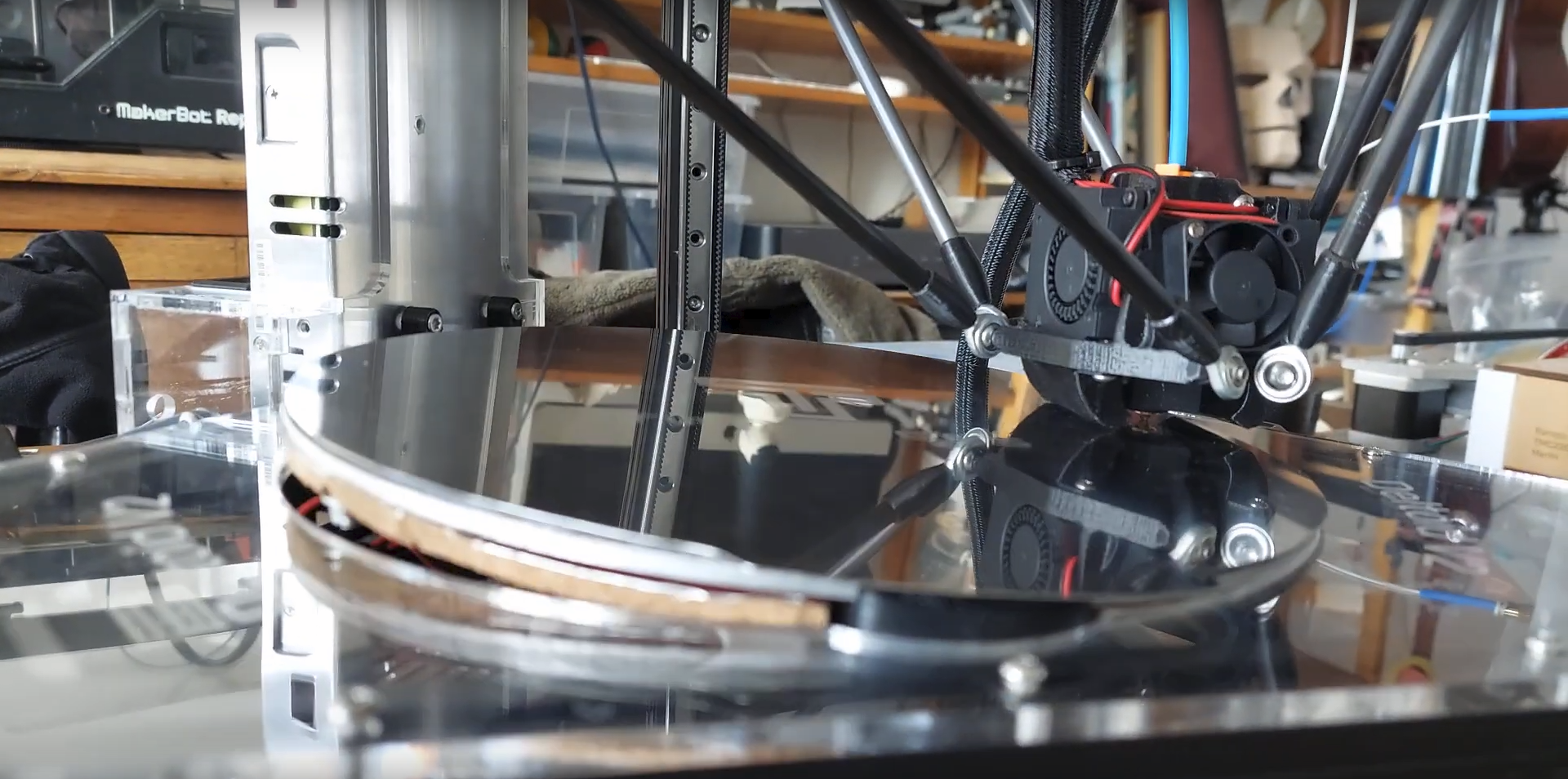
M558 P5 R0 C"!probe" H2 F500 T7200 B1Howeverrrrrr, despite having a super sensitive probing setup and slower probing, the nozzle now literally pushes so hard into the bed that one side flips up. This takes an extreme amount of force to to by hand, so it's clear that the piezo setup is not working well.
Here's a video:
https://www.youtube.com/watch?v=QssthZMF7tUStill from the video:

So in short:
- My new probing setup is the most sensitive I've been able to craft to this day
- With the probes in the "correct orientation" (according to another user) it works worse
- Help
Here's a link where I explain how I made the probing point cloud:
https://forum.duet3d.com/post/308768This is my bed.g:
; Auto calibration routine for large delta printer
M561                    ; clear any bed transform

; If the printer hasn't been homed, home it
if !move.axes[0].homed || !move.axes[1].homed || !move.axes[2].homed
  G28

; Probe the bed and do auto calibration
G1 X0 Y140 Z10 F10000        ; go to just above the first probe point
while true
  if iterations = 10
    abort "Too many auto calibration attempts"
  G30 P0 X95.26 Y12 Z-99999 H0
  if result != 0
    continue
  G30 P1 X58.76 Y-9.93 Z-99999 H0
  if result != 0
    continue
  G30 P2 X37.98 Y-45.93 Z-99999 H0
  if result != 0
    continue
  G30 P3 X37.24 Y-88.5 Z-99999 H0
  if result != 0
    continue
  G30 P4 X0 Y-67 Z-99999 H0
  if result != 0
    continue
  G30 P5 X0 Y-24 Z-99999 H0
  if result != 0
    continue
  G30 P6 X-20.78 Y12 Z-99999 H0
  if result != 0
    continue
  G30 P7 X20.78 Y12 Z-99999 H0
  if result != 0
    continue
  G30 P8 X58.02 Y33.5 Z-99999 H0
  if result != 0
    continue
  G30 P9 X58.02 Y76.5 Z-99999 H0
  if result != 0
    continue
  G30 P10 X20.78 Y55.85 Z-99999 H0
  if result != 0
    continue
  G30 P11 X-20.78 Y55.85 Z-99999 H0
  if result != 0
    continue
  G30 P12 X-58.02 Y76.5 Z-99999 H0
  if result != 0
    continue
  G30 P13 X-58.02 Y33.5 Z-99999 H0
  if result != 0
    continue
  G30 P14 X-95.26 Y12 Z-99999 H0
  if result != 0
    continue
  G30 P15 X-58.76 Y-9.93 Z-99999 H0
  if result != 0
    continue
  G30 P16 X-37.98 Y-45.93 Z-99999 H0
  if result != 0
    continue
  G30 P17 X-37.24 Y-88.5 Z-99999 H0
  if result != 0
    continue
  G30 P15 X0 Y0 Z-99999 S8
  if result != 0
    continue
  if move.calibration.initial.deviation <= 0.04
    break
  echo "Repeating calibration because deviation is too high (" ^ move.calibration.initial.deviation ^ "mm)"
; end loop
echo "Auto calibration successful, deviation", move.calibration.final.deviation ^ "mm"
G1 X0 Y0 Z150 F10000                ; get the head out of the way
Edit:
After doing some more experimenting, I've found out that there seems to be an issue with my board not detecting a trigger correctly. The PrecisionPiezo PCB LED indicates that it is triggered but RRF doesn't stop probing movement when executing a G30.Second edit:
This issue has been solved by switching to Digital Output on the PrecisionPiezo PCB. The Analog signal doesn't seem to work correctly and barely puts out a strong enough signal to be read. -
@infiniteloop said in [Delta] Precision Piezo issues:
I actually am using it in analog mode. I think I've run out of options…
The ADC converters I know of in MCUs are relatively slow, for example, the sampling frequency of an Arduino ADC at 10 bit resolution is specified with 9.6 Hz. That means: you get about 10 measures per second. Sure, the Duets are much more responsive, but they too need a finite time for a sample. If you evaluate the data points with a script, the runtime of the script comes on top. All this accounts for a rather limited resolution over time.
I use a probe with a light sensor in analog mode on a Duet 2. In oder to get some kind of precision readings, I had to reduce the probing speed to 200 (F parameter of
M558). Note that I use the generic setup withM558, just one sensor, no (interpreted) script involved. So I strongly recommend to try a probing speed way below your F500.Now there are two things I can think of trying, the first one will be to isolate all the sensor wires as it looks like there is interference that is sending false readings, however I have no idea how to make isolated wires in the first place anyway.
You can either cannibalise shielded USB cables (not all of them are shielded), or use audio input cables - those for microphones and other sources with low signal strength are always shielded.
Thanks for your tips. I have seemed to solve the problem by switching to Digital Output on the PrecisionPiezo PCB and then tuning the VR2 setting on the PCB. It's not perfect, but it's close enough.
After this I finally activated my DIY oscilloscope that I built years ago and measured the Analog signal and it only fluctuates a few mV when triggered, so the issue is probably with the Analog signal coming from the PrecisionPiezo PCB.
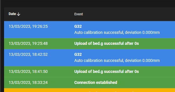
With the fixed setup I now achieve this autocalibration measurement first try:
Calibrated 8 factors using 18 points, (mean, deviation) before (-0.120, 0.029) after (0.000, 0.022) Auto calibration successful, deviation 0.022mmNormally it had to probe at least 5 or 6 times before it would even start, and I had to raise the tolerances. I can't imagine all that pounding of the hotend onto the bed has been good to my machine so I hope that nothing got damaged. Due to issues I had to remake the diagonal rods three!!! times and I was getting really demotivated
 But somehow I pulled through and managed to finish the build.
Is there some place where we can share out DIY machines in some kind of showcase subforum?
-
@Acid Are you sure, that every of the three piezo is working correctly? It can be, that two triggers with pushing and one with releasing.
-
@cosmowave said in [Delta] Precision Piezo issues:
@Acid Are you sure, that every of the three piezo is working correctly? It can be, that two triggers with pushing and one with releasing.
Hello, yes, I've also tested them individually. I went through every possible option and I'm thinking the issue now lies with how my controller interprets the signal from the PrecisionPiezo PCB.
-
@Acid Eventually you can try to use the piezos in analog mode.
Perhaps it helps to find the root cause. -
@cosmowave said in [Delta] Precision Piezo issues:
@Acid Eventually you can try to use the piezos in analog mode.
Perhaps it helps to find the root cause.Hi, I actually am using it in analog mode. I think I've run out of options and will try to replace the board with another one to see if this improves anything.. Sadly.
I noticed the analog input doesn't register the values correctly so I am suspecting the ADC on my current board might be malfunctioning somehow. It worked correctly before, and there is no issue with interference of any type. In DWC the readings do not correctly update, and despite using it in analog mode, it looks like it's in '0/1' mode, as if it only registers 0 or 1000, and it only registers 1000 if I punch the bed plate.
A short update:
It seems that when using the PCB in digital mode, it performs well, but it gets negative readings sometimes. I have tried adusting the sensitivity, but that makes it so that the nozzle pushes down the bed.Now there are two things I can think of trying, the first one will be to isolate all the sensor wires as it looks like there is interference that is sending false readings, however I have no idea how to make isolated wires in the first place anyway.
The other option for me would be to shorten the wires. Do the precisionpiezo wires have to all be the same length when using an underbed piezo setup?
-
Forgive me for not being helpful here but I went through the pain of dealing with precision piezo sensors. I struggled with this for considerable time. Results ran from being incredible sensitive to pushing down onto the bed with my printer nozzle and displacing the bed. In my case I was using a single sensor in the mount of the printhead. The concept of direct sensing of nozzle on print bed with no offsets to worry about was incredibly enticing and made just soooo much sense.
Your picture of the bed being tilted up on one side brought back a lot of (negative) thoughts about the piezo way of sensing z zero. The frustrating part was that in some locations sensing was incredibly sensitive while in other places the sensing was useless and the bed got displaced. All of this with a single sensor on a single setup!
I did try an alternate sensor with similar issues. One theory that I never fully explored but that doesn't apply to your arrangement was that possibly the umbilical from the frame to the printhead caused different forces to develop at different locations of the printhead in it's travels. The frustrating thing was that in some setups (this is over a longer period of time) the piezo seemed to perform very well indeed. Unfortunately this excellent performance seemed to happen only when the stars aligned just right. Nothing I did or failed to do seemed to give me results that were consistent - sometimes I tweaked it just right and things went well and then for seemingly random reasons, a number of sense positions would fail in a "let's see if this bed can be pushed to china" mode. Other times it seemed that the sensor could feel air movements of me moving past the printer without any direct physical contact.
I ended up with replacing the piezo system with a BLTouch system. While accuracy/sensitivity didn't seem as good as with the piezo, I got consistent results and those results were a lot more useful than what the piezo setup got me.To sum it up, I think a piezo sensing setup can work incredibly well, it can also work incredibly bad and I was not able to bring any sort of consistency into my setup (Creality CR10-S5) no matter what I tried. I wish you the best of luck but would like to point out that sometimes one can not overcome technological issues and one must face the conclusion that the technology being used is just not ready for prime time.
-
I actually am using it in analog mode. I think I've run out of options…
The ADC converters I know of in MCUs are relatively slow, for example, the sampling frequency of an Arduino ADC at 10 bit resolution is specified with 9.6 Hz. That means: you get about 10 measures per second. Sure, the Duets are much more responsive, but they too need a finite time for a sample. If you evaluate the data points with a script, the runtime of the script comes on top. All this accounts for a rather limited resolution over time.
I use a probe with a light sensor in analog mode on a Duet 2. In oder to get some kind of precision readings, I had to reduce the probing speed to 200 (F parameter of
M558). Note that I use the generic setup withM558, just one sensor, no (interpreted) script involved. So I strongly recommend to try a probing speed way below your F500.Now there are two things I can think of trying, the first one will be to isolate all the sensor wires as it looks like there is interference that is sending false readings, however I have no idea how to make isolated wires in the first place anyway.
You can either cannibalise shielded USB cables (not all of them are shielded), or use audio input cables - those for microphones and other sources with low signal strength are always shielded.
-
@infiniteloop said in [Delta] Precision Piezo issues:
I actually am using it in analog mode. I think I've run out of options…
The ADC converters I know of in MCUs are relatively slow, for example, the sampling frequency of an Arduino ADC at 10 bit resolution is specified with 9.6 Hz. That means: you get about 10 measures per second. Sure, the Duets are much more responsive, but they too need a finite time for a sample. If you evaluate the data points with a script, the runtime of the script comes on top. All this accounts for a rather limited resolution over time.
I use a probe with a light sensor in analog mode on a Duet 2. In oder to get some kind of precision readings, I had to reduce the probing speed to 200 (F parameter of
M558). Note that I use the generic setup withM558, just one sensor, no (interpreted) script involved. So I strongly recommend to try a probing speed way below your F500.Now there are two things I can think of trying, the first one will be to isolate all the sensor wires as it looks like there is interference that is sending false readings, however I have no idea how to make isolated wires in the first place anyway.
You can either cannibalise shielded USB cables (not all of them are shielded), or use audio input cables - those for microphones and other sources with low signal strength are always shielded.
Thanks for your tips. I have seemed to solve the problem by switching to Digital Output on the PrecisionPiezo PCB and then tuning the VR2 setting on the PCB. It's not perfect, but it's close enough.
After this I finally activated my DIY oscilloscope that I built years ago and measured the Analog signal and it only fluctuates a few mV when triggered, so the issue is probably with the Analog signal coming from the PrecisionPiezo PCB.
With the fixed setup I now achieve this autocalibration measurement first try:
Calibrated 8 factors using 18 points, (mean, deviation) before (-0.120, 0.029) after (0.000, 0.022) Auto calibration successful, deviation 0.022mmNormally it had to probe at least 5 or 6 times before it would even start, and I had to raise the tolerances. I can't imagine all that pounding of the hotend onto the bed has been good to my machine so I hope that nothing got damaged. Due to issues I had to remake the diagonal rods three!!! times and I was getting really demotivated
 But somehow I pulled through and managed to finish the build.
Is there some place where we can share out DIY machines in some kind of showcase subforum?
-
 undefined Acid marked this topic as a question
-
 undefined Acid has marked this topic as solved
-
@Acid said in [Solved][Delta] Precision Piezo issues:
Is there some place where we can share out DIY machines in some kind of showcase subforum?
Yes, in the category "My Duet controlled machine".
-
I just wanted to add that I have once again redesigned part of the bed and replaced the cables with shielded and grounded cables and now the leveling process is truly painless.
The only issue being that I might've set the sensitivity too high, so with long probing sessions it might pick up a false reading, but to minimize issues I have redesigned the probing pattern and limited the amount of points to 9 instead of 18. 18 points is overkill. And with 9 points I get flawless results:

Because I have seen a lot of topics about this that do not always explain the solution I will soon dedicate some of my time to do a showcase of my machine and explain in-depth how I have tackled some of the problems that came with the piezo leveling setup. I'll also try to go into the program I designed to generate the probing points for the auto calibration.
On top of that this machine uses three levers that function as a proxy to the endstops. It's a flexible joint lever which might be of interest to some users here. I wanted a lever so I could reach the maximum height on this machine, since placing the endstop between the top vertexes and the MGN12 cart would cause me to lose around 20mm of print height. Now the lever sits near the top and triggers the endstop when the cart hits the lever. In other words, the endstop has its button pointing up, so it is reversed to traditional Delta endstop positions.
A printer is never finished, it's alive.
Thanks again for all the help.