Bed leveling problems
-
@tomasl
The first measuring point is at the top center of the print bed, then the other two measuring points at the bottom at each corner of the print bed, right!?Could it possibly be that the measuring surface of the IR probe protrudes above the edge of the glass plate?
In order to determine the exact measuring area of the IR probe, I glued a sewing thread to my print bed exactly in the X direction and later exactly in the Y direction with some adhesive tape on the ends of the sewing thread.
Then I raised the print head very finely in the Z direction so that the IR probe no longer triggered.
Now I ran the nozzle exactly over the sewing thread and noted the position and then ran the IR probe over these sewing threads and noted the area where the IR probe triggered and then took the middle.Example... IR probe triggers from X55.00 to X57.00 so I noted X56.00.
For example, at X59.40, the tip of the nozzle was directly above the sewing thread.
Now I was able to determine the exact offset of the IR probe.
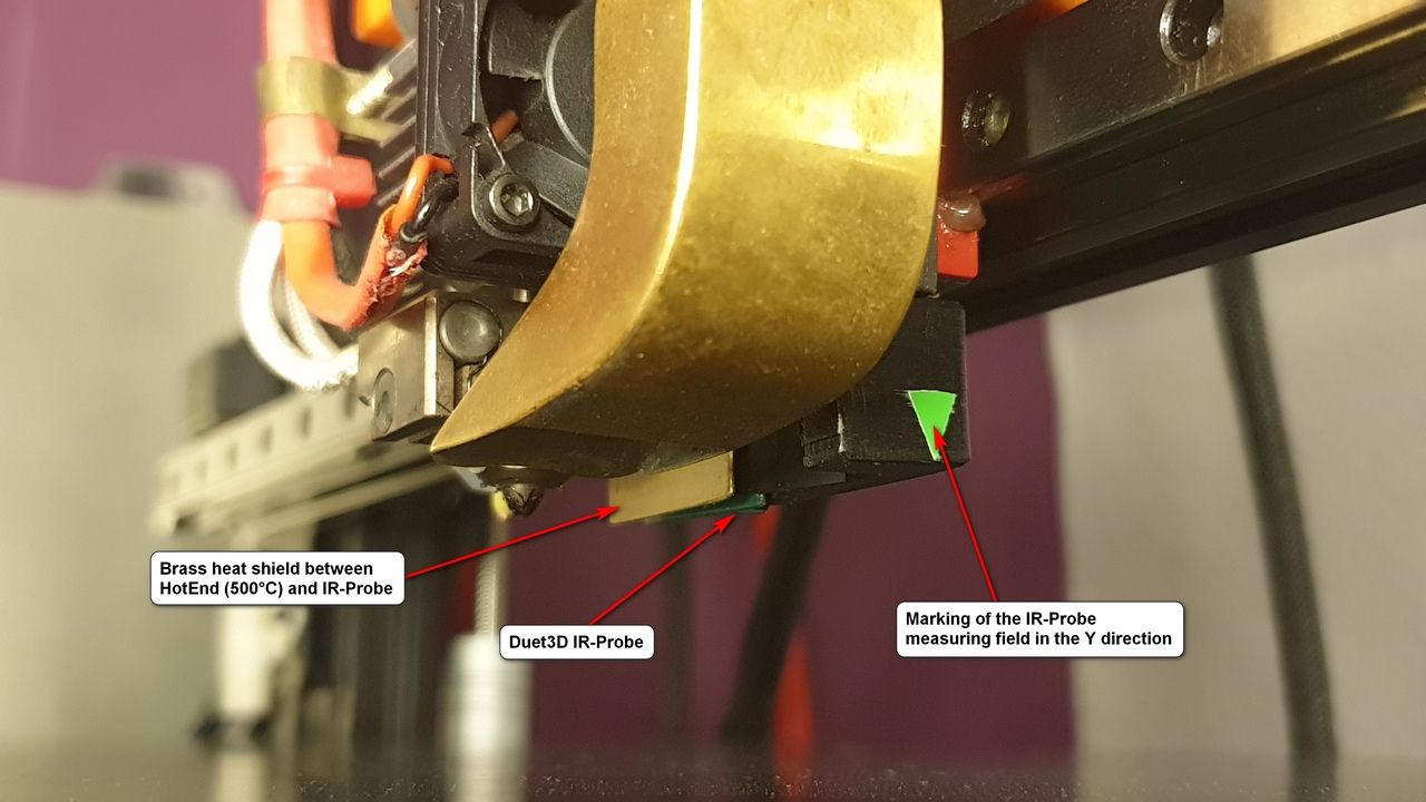
I then did the same with the Y axis.In addition, I stuck a small mark on the print head at the exact points (see photo) to immediately recognize the scanning area of the IR probe.
In the X-direction it is exactly behind the nozzle, so no second marking was necessary for this.
Check if the scanning surface of the IR probe is not outside the print bed at the first measuring point where the problems occur.
Google Translate
--- Original Text ---Der erste Messpunkt ist oben mittig vom Druckbett, dann die beiden anderen Messpunkte unten an jeder Ecke vom Druckbett, richtig !?
Könnte es eventuell sein das die Messfläche des IR-Probe oben über den Rand der Glasplatte hinaus ragt ?
Ich habe, um die exakte Messfläche vom IR-Probe zu ermitteln, auf mein Druckbett einen Nähfaden exakt in X-Richtung und später exakt in Y-Richtung mit etwas Klebeband an den Enden des Fadens, auf das Druckbett geklebt.
Dann habe ich den Druckkopf sehr fein in Z-Richtung angehoben so dass der IR-Probe nicht mehr auslöste.
Jetzt bin ich mit der Düse exakt über den Faden gefahren und habe mir die Position notiert und bin dann mit dem IR-Probe über diesen Nähfäden gefahren und habe mir den Bereich notiert wo der IR-Probe ausgelöst hat und habe dann die Mitte genommen.Beispiel... IR-Probe löst von X55,00 bis X57,00 aus, also notierte ich mir X56,00.
Die Düsenspitze war zB bei X59,40 direkt über dem Faden.
Nun konnte ich den exakten Offset des IR-Probe ermitteln.
Das gleiche habe ich dann mit der Y-Achse gemacht.Zusätzlich habe ich auf dem Druckkopf an den exakten Stellen ein kleine Markierung am Druckkopf aufgeklebt (siehe Foto), um die Abtastfläche des IR-Probe optisch sofort zu erkennen.
In X-Richtung ist es exakt hinter der Düse, also war dafür keine zweite Markierung notwendig.Prüfe mal bei Dir, ob die Abtastfläche des IR-Probe beim ersten Messpunkt, wo es zu den Problemen kommt, nicht außerhalb vom Druckbett ist.
-
Managed to crack the glass, so I need to sort that out before I can continue.
-
@tomasl
If you absolutely want to print on glass and don't allow any other surface, then get a thin mirror.
If you then move the IR-Probe down a bit, it should work fine.However, glass is not a good conductor of heat and is not an ideal surface for an IR-Probe, so I would recommend switching to a different printing surface.
I use the Blackprint magnet system from Printbay (printbay.eu) and have been very satisfied with it for years.
The plate is almost indestructible and therefore matt black without any imprints or writing.
Definitely looks better than a red heating mat with white prints.
Google Translate
--- Original Text ---Wenn Du unbedingt auf Glas drucken willst und keine andere Oberfläche zu lässt, dann besorge Dir einen dünnen Spiegel.
Wenn Du dann noch den IR-Probe etwas nach unten versetzt, sollte es gut funktionieren.Glas ist aber kein guter Wärmeleiter und keine ideale Fläche für einen IR-Probe, von daher würde ich Dir empfehlen auf eine andere Druckoberfläche zu wechseln.
Ich nutze das Blackprint Magnetsystem von Printbay (printbay.eu) und bin damit seit Jahren sehr zufrieden.
Die Platte ist fast unkaputtbar und alsolut mattschwarz ohne jegliche Aufdrucke und Schriften.
Sieht auf jeden Fall besser aus als eine rote Heizmatte mit weißen Aufdrucken.
-
@norder
Well, I have been thinking about that.
The bed is a 4 mm AL-plate, on top of that some insulation, the PCB heater and then the glass.
Now, as it transpired, I do have a couple of self adhesieve silicone foil heaters (230V).
they are either 1300W or 400W each, dont know at the moment, and acouple of 40 Amp SSRs lying around.
So the idea is to skip the glass and the pcb heater.
Connect the SSR to the Dutett, and use the AL-plate alone with the heater sticked at the bottom.
I have to cut a groove in the AL-plate for the temp sensor obviously.
Stick some Creality build tak on the top of the AL-plate.
Should work, or? -
@tomasl
That should work so far.
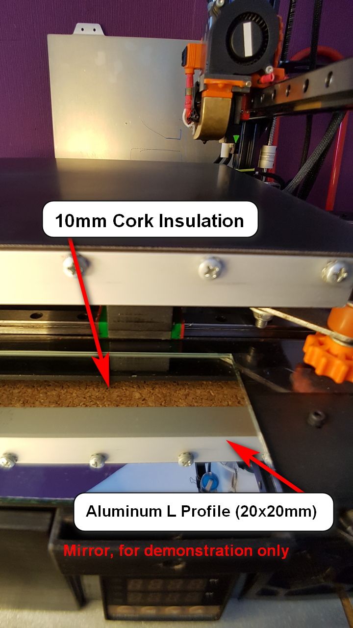
I have an 8mm AL-Plate, including a silicone heating mat (24 volts) and this is then insulated with a 10mm thick cork plate.
I glued the cork to the heating mat with silicone glue (durable up to 350°C).
In the end there was an L-shaped border made of aluminum rails around the print bed... screwed to the sides of the 8mm aluminum plate and thus holding the cork plate at the edges.
To me it looks a little nicer like this instead of the visible cork board.
I still see a problem with your conversion campaign... if the Build-Tak plate has to be replaced, you have to loosen the adhesive again and again.
And since you can't take the Build-Tak off, you have to use a putty knife to loosen the printed parts, increasing the risk of damaging the Build-Tak.I would therefore recommend a magnetic plate that you stick to the 4mm aluminum plate.
You also have the option of using a different printing plate (PEI, FR4, rough or smooth...), depending on the filament and the desired surface of the printed part.I think you'll get annoyed later if you glue the Build-Tak tight.
Google Translation
--- Original Text ---Das sollte soweit funktionieren.
Ich habe eine 8mm AL-Platte, darunter eine Silikon-Heizmatte (24 Volt) und diese ist dann mit einer 10mm dicken Platte aus Kork isoliert.
Den Kork habe ich mit Silikonkleber (bis 350°C haltbar) auf die Heizmatte geklebt.
Am Ende kam noch eine Umrandung aus Aluschienen im L-Form um das Druckbett herum... verschraubt an den Seiten der 8mm Aluplatte und hält somit die Korkplatte an den Rändern.
Für mich sieht es so etwas schöner aus, anstelle der sichtbaren Korkplatte.Ein Problem sehe ich da noch bei Deiner Umbau Aktion... wenn die Build-Tak Platte einmal ausgetauscht werden muss, musst Du den Kleber immer wieder lösen.
Und da Du die Build-Tak nicht herunter nehmen kannst, musst Du zum lösen der Druckteile einen Spachtel nehmen, was die Gefahr erhöht die Build-Tak zu beschädigen.Ich würde Dir daher eine Magnetplatte empfehlen die Du auf die 4mm Aluplatte klebst.
So hast Du auch die Möglichkeit eine andere Druckplatte (PEI, FR4, Rauh oder Glatt...) zu nehmen, also je nach Filament und Wunsch der Oberfläche des Druckteils.Ich glaube Du wirst Dich später ärgern wenn Du die Build-Tak fest verklebst.
-
@tomasl said in Bed leveling problems:
I have to cut a groove in the AL-plate for the temp sensor obviously.
This groove is in my cork
-
@norder
Ok, thanks for the input.
Question is, if I can use the AL-plate directly, until I get the magnetic stuff, Painting it black, and use PVA-glue on it -
@tomasl
Sure, why not.
I wouldn't paint the aluminum plate though.
Cover it with tape and print on it.
Bluetape should be good for PLA and PETG.
Clear packaging tape is good for PC (polycarbonate) and may also be good for PA (nylon).If you have different tapes... stick them all next to each other on the aluminum plate and print a strip across these tapes to test which tape works best for each filament.
Google Translate
--- Original Text ---Klar, warum nicht.
Ich würde die Aluplatte aber nicht lackieren.
Beklebe sie mit Tape und drucke da drauf.
Bluetape sollte gut für PLA und PETG sein.
Durchsichtiges Paketklebeband ist gut für PC (Polycarbonat) und eventuell auch für PA (Nylon).Wenn Du verschiedene Klebebänder hast... klebe sie alle nebeneinander auf die Aluplatte und drucke einen Streifen quer über diese Klebebänder um zu testen welches Klebeband für das jeweilige Filament am besten geeignet ist.
-
@norder
Will do, thanks. -
@tomasl
So you don't have to paint the aluminum plate black especially for the IR probe.
It works perfectly on metal surfaces.To test it, I placed a spring steel plate with a PEI coating (you can see it in the background in the last photo) upside down on the magnetic plate, and the repeatability of the IR probe has never been better than on this surface.
Metallic, reflective surfaces such as spring steel and I assume an aluminum plate should work very well.So you could spread the PVA glue directly onto the aluminum plate.
I don't think there can be any problems there.Google Translate
--- Original Text ---Du musst die Aluplatte also nicht extra für den IR-Probe schwarz lackieren.
Der funktioniert perfekt auf Metall Oberflächen.Ich habe zum Test mal eine Federstahlplatte mit PEI Beschichtung (auf dem letzten Foto im Hintergrund zu sehen) verkehrt herum auf die Magnetplatte gelegt, und die Wiederholgenauigkeit des IR-Probe war noch nie so gut wie auf diesem Untergrund.
Metallisch spiegelnde Oberflächen wie zB Federstahl und ich nehme an auch die einer Aluplatte sollte sehr gut funktionieren.Du könntest also den PVA-Kleber direkt auf die Aluplatte verteilen.
Ich glaube nicht dass es da zu Problemen kommen kann. -