Another Non-Linear Extrusion Post
-
I am trying myself at calibrating the M592 non-linear extrusion feature and ended up with some questions (at the bottom).
The setup
I opted to do the measurement "in-print" on some "1-wall, rounded corner testcube spirals" with 0.6 mm wide, overextruded walls.

This should ensure that I am not getting any artifacts due to accelerations and allows me to take several measurements per print speed. Print speeds were varied from 10-90 mm/s corresponding to flow rates of roughly 1-10 mm³/s which should be possible with a stock E3D V6 hotend.
Each print was measured six times, for a total of 54 measurements.
The next step might be a bit controversial, but as I used Cura to slice those parts and Cura uses a simple
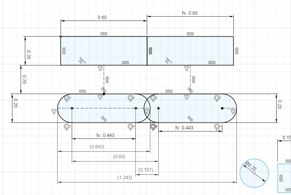
layer_height * extrusion_widthmodel to calculate the required volume I assumed a target width of 0.643 mm to compare the measured extrusion width to:
(both the
layer_height * extrusion_widthand the "wurst" at the bottom share the same area)the results
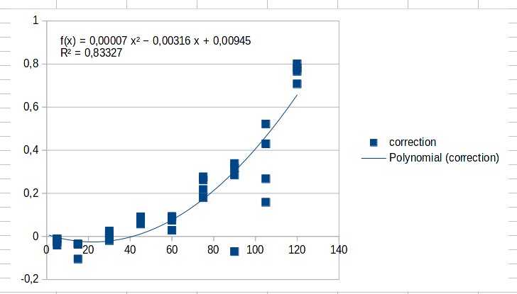
I did the above several times and I always arrive at negative A factors. E.g:

(The fit uses the A term to adjust for too much extrusion at the lower speeds)
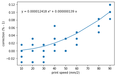
To mitigate that, I adjusted the flow rates via
M221and fitted another model (this time excluding the C term):
Judging from that there is somewhat significant underextrusion of about 10% happening in my setup that
M592should be able to mitigate.Questions
- I assume
final_volume = slicer_volume * M221 * (1 + M592), is that correct? - Can we at this point assume that speed and volume correlated with at simple
extrusion=B*speed²relation, losing theAfactor? - Somewhat tangential, but is my "equal volume" line width calculation above reasonable?
- As there are devices that actually measure the amount of extruded filament [1] ... wouldn't they have triggered regularly when confronted with non-linear extrusion. Could they be used in a control loop?
[1] https://duet3d.dozuki.com/Wiki/Duet3dFilamentMonitor_RotatingMagnetVersion
- I assume
-
One completely tangential side note that came out of the cross-area modeling above is that Curas simple rectangle (
layer_height*extrusion_width) model is perfectly viable for lines that have "neighbors" on both sides. The combined extrusion will perfectly fill the space between the lines.Where this falls short is at the outer lines, where the rounded corners will overshoot the intended line width. With a target width of 0.4 mm this model predicts an actual extrusion of 0.443 mm which corresponds to a necessary flow rate reduction of ~90% ... which is more or less exactly what I have measured every time I do flow rate calibrations.
The formula I use for this is:
target_volume = target_layer_height * target_extrusion_width
equivalent_circle_to_circle_width = (target_volume - ((0.5 * target_layer_height)^2 * pi)) / target_layer_height
actual_extrusion_width = equivalent_circle_to_circle_width + target_layer_height
In the end that means that 0.2 mm layer height prints from Cura will always be larger by
0.043 / 2 = 0.0215 mmin the XY plane. -
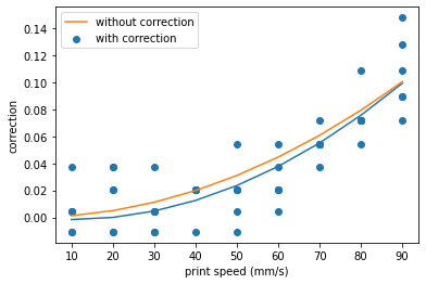
I am back with the actual results:

I ran the exact same GCode with
M221andM592enabled and measured all prints again.There seems to be an effect there, at least the 10-30 mm/s range does look flatter to me. But it is hard to say anything definitive compared to the measurement noise.
On the other hand, if 90 mm/s print speed (~10 mm³/s flow rate) is a hard maximum for the V6 hotends increasing the extrusion rate should not really do anything there. So maybe my calibration routine is somewhat flawed.