Cannot Connect to Duet 3 Web Control
-
@frank-0 said in Cannot Connect to Duet 3 Web Control:
@phaedrux Is the latest stable release not 3.3? What happens if the SD card has 3.3 and the board has 3.4?
The SD card doesn't really hold firmware in any meaningful way other than it has the bin files available to be flashed to the board itself. We can go back to 3.3 once you have solid access to dwc again.
-
@frank-0 said in Cannot Connect to Duet 3 Web Control:
@phaedrux Made a new SD card and have this on it.
 .
.
Is this all I need?No I listed the needed folders above. In addition to those you'll actually need a firmware folder as well.
Technically those are the bare minimum. But we should create the rest so it doesn't complain.
-
@phaedrux Could you point me back to where you listed the folders I need? I don't see it, I must be blind. I download the 3.3 firmware and then just put it in the www folder?
-
@phaedrux said in Cannot Connect to Duet 3 Web Control:
@frank-0 said in Cannot Connect to Duet 3 Web Control:
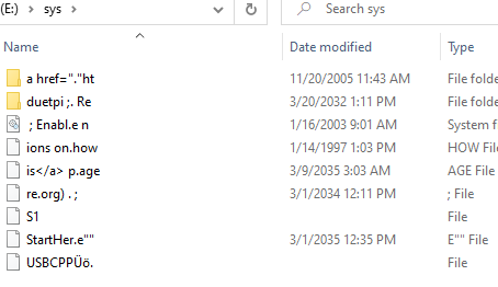
@kb58 After using Bossa to reset my firmware, I cannot find the config.g file. The sys folder changed to this

I have never seen anything like that before.
I suggest you get a clean new SD card, format it as FAT32, and then start fresh from there.
Create the following folders
sys
macros
www
gcodes
menu
filamentsCreate a fresh config file set from here: https://configtool.reprapfirmware.org/Start
Fill out the info to the best of your knowledge. We just want a starting point.
What firmware bin file version did you use to flash with Bossa? 3.3?
https://github.com/Duet3D/RepRapFirmware/releases/download/3.3/DuetWebControl-SD.zip
Download that zip file and extract it into the /www/ folder.
That should get your SD card back to a working state.
Here it is.
-
@phaedrux What should be in the macros/gcodes/menu/filaments folder? I can make the folders, but Im not sure what to put in them.
-
@frank-0 Nothing. They will be empty.
The gcodes folder is where your uploaded print files will go. menu is a folder for menu files when using a rotary encoder display. And filaments is used to store filament profiles if you set them up. They just need to exist otherwise you'll get a little warning that they are mising.
Oh, and the firmware folder is where firmware files will go in future
-
@phaedrux I got this set up and have this currently:

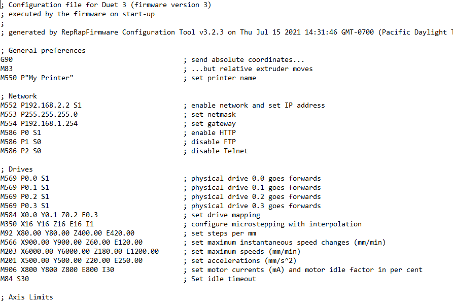
This is my config.g file:

and I extracted 3.3 firmware into www folder. YAT still doesn't really work. M552 S1 P192.168.2.2 just responds with ok, not network running.
-
@frank-0 There is also no lights lit up at bottom of the ethernet port
-
@frank-0 said in Cannot Connect to Duet 3 Web Control:
and I extracted 3.3 firmware into www folder.
Don't do that.
@frank-0 said in Cannot Connect to Duet 3 Web Control:
M552 S1 P192.168.2.2 just responds with ok,
If you send M552 what does it say?
@frank-0 said in Cannot Connect to Duet 3 Web Control:
I got this set up and have this currently:
Don't forget to add a folder called firmware.
-
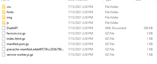
@phaedrux www folder :

YAT literally just says "ok", like in the images above from a while ago.
Should I just make an empty folder called "firmware"?
-
Are you able to ping 192.168.2.2?
What IP is your computer using?
Have you tried a different cable?
Do the lights on the ethernet port light up if you connect to your router instead? even briefly?
-
@phaedrux Timed out, is unreachable. Can't ping it
-
What IP is your computer using?
Have you tried a different cable?
Do the lights on the ethernet port light up if you connect to your router instead? even briefly?
-
@phaedrux Computer is using an assigned IP address I changed in the control panel. It is 192.168.2.1. I tried different cable and no the lights don't light up at all.
-
@frank-0 said in Cannot Connect to Duet 3 Web Control:
I tried different cable and no the lights don't light up at all.
Not with the router either?
-
@phaedrux Yeah doesn't light up with either computer or router
-
Alright, I think we've solved the firmware problem since it's able to speak with YAT now and it is taking and executing commands.
I think we have the SD card issue solved.
Can you post your current config.g from the /sys/ folder please?
-
-
Copy and paste the text please.
-
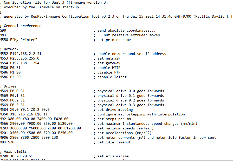
@phaedrux ; Configuration file for Duet 3 (firmware version 3)
; executed by the firmware on start-up
;
; generated by RepRapFirmware Configuration Tool v3.2.3 on Thu Jul 15 2021 14:31:46 GMT-0700 (Pacific Daylight Time); General preferences
G90 ; send absolute coordinates...
M83 ; ...but relative extruder moves
M550 P"My Printer" ; set printer name; Network
M552 P192.168.2.2 S1 ; enable network and set IP address
M553 P255.255.255.0 ; set netmask
M554 P192.168.1.254 ; set gateway
M586 P0 S1 ; enable HTTP
M586 P1 S0 ; disable FTP
M586 P2 S0 ; disable Telnet; Drives
M569 P0.0 S1 ; physical drive 0.0 goes forwards
M569 P0.1 S1 ; physical drive 0.1 goes forwards
M569 P0.2 S1 ; physical drive 0.2 goes forwards
M569 P0.3 S1 ; physical drive 0.3 goes forwards
M584 X0.0 Y0.1 Z0.2 E0.3 ; set drive mapping
M350 X16 Y16 Z16 E16 I1 ; configure microstepping with interpolation
M92 X80.00 Y80.00 Z400.00 E420.00 ; set steps per mm
M566 X900.00 Y900.00 Z60.00 E120.00 ; set maximum instantaneous speed changes (mm/min)
M203 X6000.00 Y6000.00 Z180.00 E1200.00 ; set maximum speeds (mm/min)
M201 X500.00 Y500.00 Z20.00 E250.00 ; set accelerations (mm/s^2)
M906 X800 Y800 Z800 E800 I30 ; set motor currents (mA) and motor idle factor in per cent
M84 S30 ; Set idle timeout; Axis Limits
M208 X0 Y0 Z0 S1 ; set axis minima
M208 X230 Y210 Z200 S0 ; set axis maxima; Endstops
; WARNING: No endstops configured; Z-Probe
M558 P0 H5 F120 T6000 ; disable Z probe but set dive height, probe speed and travel speed
M557 X15:215 Y15:195 S20 ; define mesh grid; Heaters
M308 S0 P"temp1" Y"thermistor" T100000 B4138 ; configure sensor 0 as thermistor on pin temp1
M950 H0 C"out0" T0 ; create bed heater output on out0 and map it to sensor 0
M307 H0 B1 S1.00 ; enable bang-bang mode for the bed heater and set PWM limit
M140 H0 ; map heated bed to heater 0
M143 H0 S120 ; set temperature limit for heater 0 to 120C
M308 S1 P"temp0" Y"thermistor" T100000 B4138 ; configure sensor 1 as thermistor on pin temp0
M950 H1 C"out2" T1 ; create nozzle heater output on out2 and map it to sensor 1
M307 H1 B0 S1.00 ; disable bang-bang mode for heater and set PWM limit
M143 H1 S280 ; set temperature limit for heater 1 to 280C; Fans
M950 F0 C"out4" Q500 ; create fan 0 on pin out4 and set its frequency
M106 P0 S0 H-1 ; set fan 0 value. Thermostatic control is turned off
M950 F1 C"!out6" Q500 ; create fan 1 on pin !out6 and set its frequency
M106 P1 S1 H1 T45 ; set fan 1 value. Thermostatic control is turned on; Tools
M563 P0 D0 H1 F0 ; define tool 0
G10 P0 X0 Y0 Z0 ; set tool 0 axis offsets
G10 P0 R0 S0 ; set initial tool 0 active and standby temperatures to 0C; Custom settings are not defined
