Anybody wants a stepper motor analyzer?
-
@zapta Cool thank you! I appreciate the feedback and the offer. Once I get mine done I'll give you a holler.
-
Hey @Zapta, after using it for a while now, I would love to change at least one configuration aspect: A lower scale screen for the steps chart.
When I have it hooked up to my extruder motor, even at the higher end of my print speeds, I only use about 600 of the 1k step scale, with the current time scaling.
For really looking at how linear advance is (or is not) working, a much tighter scale would be awesome. Maybe a [300 step / 10 sec] screen, or even [150 step / 5 sec]
It looks like steps_chart_screen.cpp handles this:

But while Y scale might be set here (and labeling), it looks like the X time scale is defined elsewhere.
Questions:
- Is there a memory limit that would prevent adding say 2 more chart axis configs to this screen?
- Would you be interested in kicking out a new firmware revision that added these?
- If not, could you offer any guidance on which files need to be changed, and any thing else about compiling and uploading that is important?
Thanks!
-
Hi @ccs86, thanks for the feedback.
I created a release candidate with that include a third scale 0-200 steps. Please try to flash to your device and see if it works.
To flash, disconnect the usb connector, press and hold the button at the back (through the hole) and connect to your computer. This should add a new disk drive to your computer. Download and copy APPLICATION.uf2 from the link below to that disk, wait a second or two until it completes and you are doen.
https://github.com/zapta/simple_stepper_motor_analyzer/blob/main/temp/APPLICATION.uf2
If it will work, I will make it an official release.
As for the time scale, how important is it to have it faster (e.g. 5 secs)? This change is slightly more involved if different Y scales need different time scale but doable.
EDIT: this is how the scale definitions looks now. If you have change suggestion for the other two scales please let me know.
-
@zapta said in Anybody wants a stepper motor analyzer?:
Hi @ccs86, thanks for the feedback.
I created a release candidate with that include a third scale 0-200 steps. Please try to flash to your device and see if it works.
To flash, disconnect the usb connector, press and hold the button at the back (through the hole) and connect to your computer. This should add a new disk drive to your computer. Download and copy APPLICATION.uf2 from the link below to that disk, wait a second or two until it completes and you are doen.
https://github.com/zapta/simple_stepper_motor_analyzer/blob/main/temp/APPLICATION.uf2
If it will work, I will make it an official release.
As for the time scale, how important is it to have it faster (e.g. 5 secs)? This change is slightly more involved if different Y scales need different time scale but doable.
EDIT: this is how the scale definitions looks now. If you have change suggestion for the other two scales please let me know.
@zapta Thanks my man!
It works great!
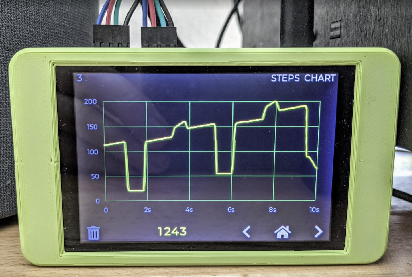
The shorter times scale (I think) would be cool, but if it's a big pain don't worry about it. Here is a simple pressure advance test, 20 - 80 mm/s, 3mm retracts.
Going to first off an actual print to see how that looks.

-
@ccs86, I published a new release with this change https://github.com/zapta/simple_stepper_motor_analyzer/releases/tag/F1.0.4
The graph looks interesting. If I understand it correctly the pressure advance doesn't start immediate after the retraction/traction, and it extrudes a little bit before it increases slope. is it so?
-
@zapta said in Anybody wants a stepper motor analyzer?:
@ccs86, I published a new release with this change https://github.com/zapta/simple_stepper_motor_analyzer/releases/tag/F1.0.4
The graph looks interesting. If I understand it correctly the pressure advance doesn't start immediate after the retraction/traction, and it extrudes a little bit before it increases slope. is it so?
I think you have it right.
Here is a video that will probably illustrate it much better than I can explain.
It starts with some alignment marks, then does a pass with no pressure advance, then PA turns on and increases for each line, and then off again for the last line.
-
@ccs86, the link didn't work for me.

-
@zapta said in Anybody wants a stepper motor analyzer?:
@ccs86, the link didn't work for me.

Link updated. Try again.
-
@ccs86, very interesting. Those PA 'pulses' is not how I imagined PA.
It explains the extreme noises I got at the time when I tried high PA values with a 600mm bowden printer. The stepper was so erratic that I had to install it on RC rubber dumpers. Eventually I switched to a direct drive and the problem solved.
I wonder if PA has one 'natural' profile or if different firmware developers come with different profiles. There are many degrees of freedom in shaping the profile which we reduce to a single number.
-
@zapta said in Anybody wants a stepper motor analyzer?:
@ccs86, very interesting. Those PA 'pulses' is not how I imagined PA.
It explains the extreme noises I got at the time when I tried high PA values with a 600mm bowden printer. The stepper was so erratic that I had to install it on RC rubber dumpers. Eventually I switched to a direct drive and the problem solved.
I wonder if PA has one 'natural' profile or if different firmware developers come with different profiles. There are many degrees of freedom in shaping the profile which we reduce to a single number.
I have found that the current PA implementation is not useful at all on my bowden printer, and I think it's about as well-tuned as a bowden gets. I have a few thoughts on why it is missing the mark that I posted here:
https://forum.duet3d.com/topic/17752/pressure-advance-discussion-for-future-development
There are certainly different ways to implement PA, but the same basic principle is a the base: increasing volumetric extrusion rate, requires increased nozzle pressure (filament drive force). The filament drive system acts like a spring, so you can increase pressure/force with an increased spring preload (being a certain number of steps "ahead").
Klipper has a PA "smoothing" algorithm that I think would be really helpful in calming down the extruder motion. But I think bowden machines need more,
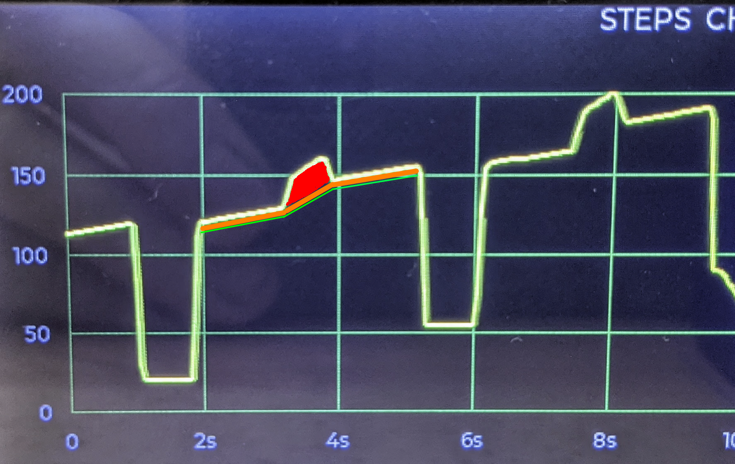
On the steps chart, you can think of the green line here as PA=0. The orange area is the steps boost for 20mm/s, and the red area the additional steps for 80 mm/s

-
Hi Zapta - nice work with the Stepper analyzer.
I would like to buy one - do you send to Denmark? And what will it cost?
many greetings
-
Hi @webhunter, build 30 units and gave to people here at cost. Currently I don't plan to build additional ones but all the files are in public domain and anybody is invited to build, including commercially.
-
-
@webhunter You can certainly get your own pcb (note, not assembled with components) from a place like JLCPCB or OshPark and build it yourself, or source assembled units from JLCPCB using the source files.
-
@webhunter, I used the files here to order the boards from JLCPCB with SMD service.
https://github.com/zapta/simple_stepper_motor_analyzer/tree/main/kicad/JLCPCB
It includes only the components they support which means that some parts you will need to order and solder yourself (the two current sensors, the two connectors, the Raspberry Pico module, and then you will need to attach and connect the TFT module). Make sure to get the exact TFT module for compatibility with the hardware and firmware.
Of course you can get bare boards and solder everything yourself but it depends on your SMD soldering skills. The TFT connectors have 0.5mm pitch and it's easy to bridge adjacent pins (and it's possible to fix if you or JLCPCB happened to bridge them).
Let me know if you have further questions.
Edit:
- When ordering from JLCPCB with SMD service, they will fix the orientation of a few components. That's normal since they assume different footprints.
- PCBWAY may provide a more complete service (with current sensors and Pico board soldered) but ordering SMD service from them is slightly more involved.
-
@zapta one Idea would be to integrate the RP2040 directly. Will Look Into that Option If i have any time
-
Hello everyone.
Just a quick update. I finally got time to build a couple of the analyzers. I will go in tonight and do some testing. Once I'm done I will have a couple available. Send me a message and let me know if you're interested.
-
@pcr, yes, using rp2040 directly would be a good move forward, considering that JLCP now carries it as a standard SMD service part.
Dustin Watts, the designer of ESP32 Tochdown (which which I copied the form factor and TFT model) mentioned recently doing something similar to his product and may have schematics to share (he is available on his Discord channel and is very open source friendly).
https://www.tindie.com/products/dustinwattsnl/esp32-touchdown/
Another good move would be to switch to a current sensor that JLCPCB carries (I found an allegro +/-5A with 5V supply and lower bandwidth one that may fit with some adaptations). Or, placing the SMD service order with PCBWAY which has access to more parts (Dustin Watt order from them and they also sponsor his YT channel)
@Th0mpy , that's awesome.
-
I have some sensors from the legacy one left. So i will build some of the pico ones.
Anyone wants one in europe
-

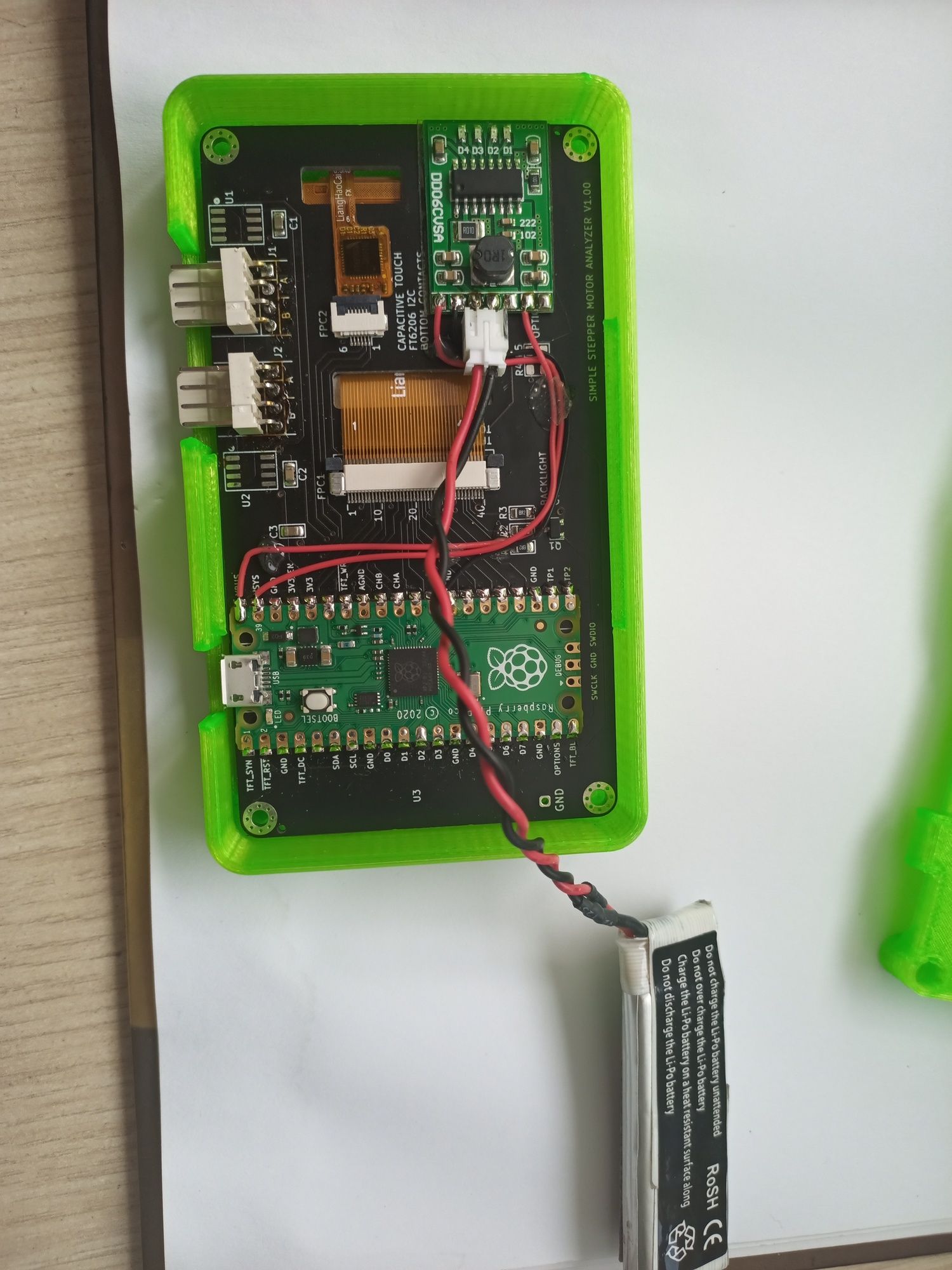
I'm working on battery powered one. Consumtion is 220mAh so around 2H autonomy. Charge and use as the same time when USB plugged. Small Housing redesign, 1mm thicker.
Still waiting sensors from china (hard to find them in europe!)