M581 not triggering pause
-
Hello,
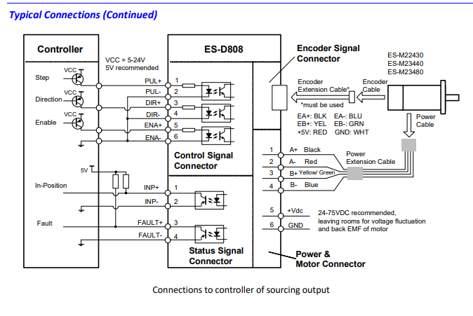
I use external stepper drivers that contain fault pins with an optocoupler that put a signal to the Duet board when in fault. Right now I put this signal (that gives a positive signal) to the e1 endstop.
My config file is as follows:
; General preferences
G90                                            ; send absolute coordinates...
M83                                            ; ...but relative extruder moves
M550 P"Artechno Printer"                       ; set printer name

; Network
M551 P"Artechno"                               ; set password
M552 S1                                        ; enable network
M586 P0 S1                                     ; enable HTTP
M586 P1 S0                                     ; disable FTP
M586 P2 S0                                     ; disable Telnet

; Drives
M569 P5 R1 S1 T5.0:5.0:5:5                                 ; physical drive 0 goes forwards
M569 P6 R1 S1 T5.0:5.0:5:5                                 ; physical drive 1 goes forwards
M569 P7 R1 S0 T5.0:5.0:5:5                                 ; physical drive 2 goes forwards
M569 P8 R1 S1 T5.0:5.0:5:5                                 ; physical drive 3 goes forwards
M584 X5 Y6 Z7 E3                               ; set drive mapping
M350 E16 I0                                    ; configure microstepping without interpolation
M92 X80.00 Y80.00 Z320.00 E410                 ; set steps per mm
M566 X900.00 Y900.00 Z12.00 E120.00            ; set maximum instantaneous speed changes (mm/min)
M203 X9000.00 Y9000.00 Z180.00 E1200.00        ; set maximum speeds (mm/min)
M201 X800.00 Y800.00 Z20.00 E200.00            ; set accelerations (mm/s^2)
M906 X800 Y800 Z800 E800 I30                   ; set motor currents (mA) and motor idle factor in per cent
M84 S30                                        ; Set idle timeout

; Axis Limits
M208 X0 Y0 Z0 S1                               ; set axis minima
M208 X1200 Y900 Z400 S0                       ; set axis maxima

; Endstops
M574 X1 S1 P"!xstop"                            ; configure active-high endstop for low end on X via pin xstop
M574 Y1 S1 P"!ystop"                            ; configure active-high endstop for low end on Y via pin ystop
M574 Z1 S2                                     ; configure Z-probe endstop for low end on Z
M581 T1 S1 P"!e1stop"							; When motor stalls, pause print

; Z-Probe
M558 P5 C"!e0stop" H5 F120 T6000             ; set Z probe type to unmodulated and the dive height + speeds
G31 P500 X0 Y0 Z1.020                          ; set Z probe trigger value, offset and trigger height
M557 X15:215 Y15:195 S50                        ; define mesh grid
I am wondering a few things:
- Do I need to use extra pins? Right now the e1stop is the only connected pin.
- I use an expansion breakout board, which changed the use of those pins. I do not have a e2stop, e3stop etc, is there a way to still use this while using the expansion breakout board?
- Is my code setup correct? I used the same pin-name used for my endstops so I thought this was correct but it is not working.
Thanks in advance.
-
are you connecting several outputs to the same input pin?
do you know what type of output it is? from it not working I'd suggest not connecting them together until you determine how to safely do so
-
@bearer it was 24v so I disconnected it.
I want to use this signal so I thought of adding a relais that activates the endstop. Should I put the ground somewhere and direct the 5V signal to the endstop. Should that work with the current M581 code?
-
24v in itself isn't a problem for the endstops, but if you have outputs of push/pull type rather than open drain with pull up you'll have issues connecting multiple outputs.
-
@bearer what do you mean by that exactly? It is a free endstop (I am not using multiple extruders so E1 is empty).
This is the diagram for the fault signals:

Looks like 5V. I am not an electrician but I thought of using this signal in a relais, that links the 5V of the endstop to the Endstop input, leaving the ground untouched. Is that a workable option?
-
should be fine to wire fault- to ground and fault+ to stp, even for multiple fault+ signals to the same stp pin.
edit: stp is the silkscreen label, the wiring diagram says e1stop, just to be clear.
edit2: by the looks of it you should use
^in the config to enable internal pull up of the endstop pin name.