3 spehre/point Delta ("Spiderbot")?
-
I came across this 3 point delta concept recently but I'm having trouble finding reviews of it:
It's discussed briefly under delta end effector stability second of the reprap wiki
There's a company out of France actually making some examples
And I found one home brew example on youtube
...but I haven't found any reviews about the tradeoffs of this design. I guess it gives less end effector wobble? But is that really a major concern?
Has anyone here played around with this concept?
-
You can get the mathematical differences with one of the calculators ( i like the openscad simulator). The optimal arm spacing is dependent on your print diameter, but you also have a trade off with printable area since you'll have to move the balls further from the center of the effector. Since you can't really go further than having the joints be over lapping, that's kind of the concept to ride that optimal point at least math wise. As for how it works out in practice, not clue but there's so many little variables in the whole system that I don't see it helping that much when there's enough knowledge about the normal configuration you can easily tease out what is probably off when your troubleshooting.
-
Hope I can help, my first printer was the SeeMeCNC Rostock MAX built up as a kit as I wanted to build a different printer from the standard cartesian ones (and also when it prints it has a very satisfying hypnotic movement). Lets just say the original Rostock MAX had plenty of issues but a great kit for learning from.
I was going to build my own but like you found the SpiderBot website many years ago and it's construction ticked all my boxes for accuracy and quality. Also, the heated chamber for ABS was a plus (this was in the days before PETG).
The biggest failing was the hardware, with a delta three stepper motors have to be driven for the axis all the time and one for the extruder. The SpiderBot had a Megatronix 8 bit board that was close to it's limits. I upgraded mine with the ultratronics (this was the 32 bit version). This upgrade of computation power was in my opinion essential for a delta.
SpiderBot also came up with a novel dual head (using a servo to cant the head) which makes printing with HIPS and ABS easy. Unfortunately, now we have PETG the SpiderBot doesn't get as much work as the ABS has a distinct odour.
The carbon fibre arms all manufactured identical lengths on a press with the ball bearings makes it more accurate than the Rostock which was rather flimsy.
If there is anything specific I can help with just let me know
-
Forgot to say, my 2nd printer was the SpiderBot.
-
@Bluemalu thanks for the response. I'd be curious what the size of the contact spheres are and if they are solid, or hollow.
I guess it seems like an obvious mechanical improvement and I'm struggling to understand why no one else seems to be copying it. I guess weight savings? Big spheres being heavy and all...
What was your impression of the 3 pt contact strategy? Was it worth the effort? Or just cool in theory but no noticeable improvement in quality?
I saw a mention of the tilting hot end on their page for the spiderbot 2.x or so...looked cool but I didn't see how their tilting mechanism worked. I don't suppose you have any photos of that do you?
-
I think the easiest answer is all of the issues related to Cartesian printers and movements were solved with pen plotters and dot matrix printers. Big companies have been able to produce the most efficient and cheap way to solve the issues so other than a moving Z platform it's virtually plug and play. Also, as I stated previously the processing power to control 4 stepper motors was right at the limit for 8 bit boards. Another disadvantage is the size of the machine, it has to be much taller than the equivalent sized cartesian due to movement required for the edges of the bed, also the bed is round rather than square / rectangular.
The Kinematic control of the head has caught up now so it's lovely and smooth, by design the head will be horizontal (although I did read of paper where they had printed in a terrain following method for the top layers, just required knowledge of the head shape to avoid clashes - this was a few years ago and I can't find any further work carried out - maybe Simplify3D V5

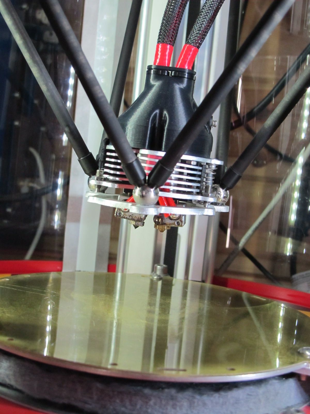
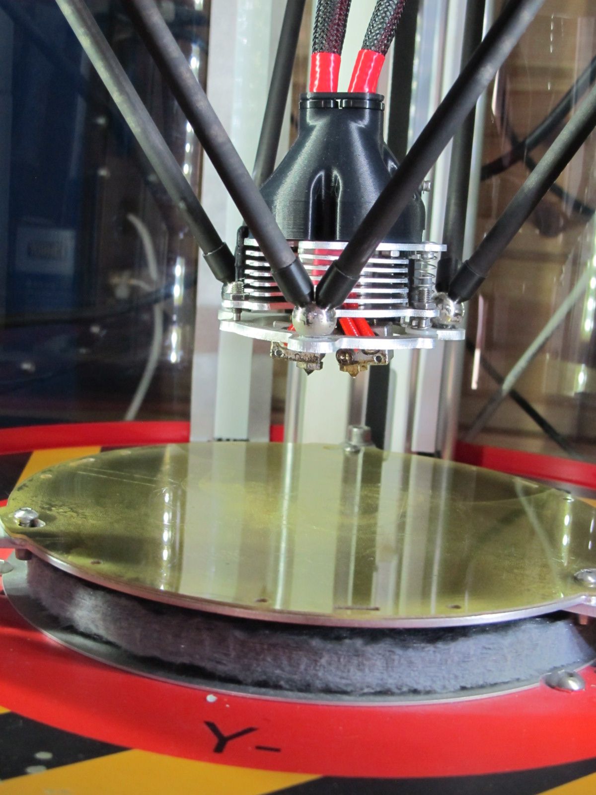
My SpiderBot is the V1.5 with various upgrades through SpiderBot and the prototype dual head. Attached are a couple of pictures, maybe best to have them side by side as the cantilever of the head via the servo is subtle but is an elegant solution to dual head woes (one of my other printers is the BigBox Dual with print heads the same height so I'm used to suffering the issues with the 1st layer).
[http://www.spiderbot.eu/spiderbot-v2-1-whats-new/?lang=en](link url)


The original design used ball bearings secured with epoxy, as the printer is used with a heated chamber this heat cycling (or my cold shed) caused them to fall off. Philippe (owner of SpiderBot) improved the design by riveting the balls onto the aluminium.
I'm more than happy with mine and the assistance I've had over the years for SpiderBot, it just doesn't get used as much due to having multiple printers and not using ABS.
It's well worth having a nosey though the older blog articles to see the engineering iterations leading up to the latest versions.