Inconsistent results with optical encoder wheel filament sensor
-
@JohnOCFII "assuming the magnetic sensor would be OK on the printer frame."
I can't see where you have your filament monitor mounted right now.
Assuming your bowden is all tight at both ends, I think it should be possible to mount the monitor back near your spool holder.
-
@alankilian said in Inconsistent results with optical encoder wheel filament sensor:
@JohnOCFII "assuming the magnetic sensor would be OK on the printer frame."
I can't see where you have your filament monitor mounted right now.
Assuming your bowden is all tight at both ends, I think it should be possible to mount the monitor back near your spool holder.
Yes, it is back by the spool holder:

-
@JohnOCFII That should work just fine if you decide to go this way.
-
@alankilian said in Inconsistent results with optical encoder wheel filament sensor:
@JohnOCFII That should work just fine if you decide to go this way.
If Tim @Filastruder has any extra bits, I might order one today with the current sale. The regular one is out of stock, but I understand that is just due to the case. My printers are precise enough that I'm sure I could get the case going.
My Digi-Key order arrived, but work has been too busy this week to open it up or to think about wiring yet.
-
@JohnOCFII The three case parts printed easily at 0.1mm layer height with PLA and printing slowly on my Rostock Max V3.2 with a 0.5 nozzle.
The only thing is the pin and guide are slightly too short on the Idler part so the bearing can drop off the filament as it moves "up" in the case.
I just installed it bearing-side in and it's fine.
If you're able to modify the .step file provided on their github repository, I would go 1mm thicker for these two polygons.
I can't figure out how to modify a .step using FreeCAD, but it's supposed to be possible. Maybe I need to spend some YouTube time this afternoon.
-
@alankilian said in Inconsistent results with optical encoder wheel filament sensor:
Your filament monitor travels inspired me to take the easy route and order the parts for a magnetic filament monitor from filastruder.
I checked with FilaStruder, and apparently you got the last one.
-
Are these discontinued? I'd like to add this to my setup but it's never been back in stock, for months now.
-
@cdthomas9 They are trying to figure out how to get the cases made.
I don't know what the issue was.
-
@cdthomas9 said in Inconsistent results with optical encoder wheel filament sensor:
Are these discontinued? I'd like to add this to my setup but it's never been back in stock, for months now.
Yes, it is an issue with the cases. I think they switched technologies (SLS to injection molded?) and COVID has somewhat slowed the process, or lowered priority.
-
@JohnOCFII I sent you a chat message with a contact at Duet3d who might be able to help you with a magnetic filament monitor parts kit.
Let me know if you didn't get the message and how to send it to you.
-
@alankilian said in Inconsistent results with optical encoder wheel filament sensor:
@JohnOCFII I sent you a chat message with a contact at Duet3d who might be able to help you with a magnetic filament monitor parts kit.
Let me know if you didn't get the message and how to send it to you.
Weird -- I get emails for message updates, but not "chat" updates -- so I hadn't seen that message.
-
@alankilian said in Inconsistent results with optical encoder wheel filament sensor:
https://www.digikey.com/en/products/detail/texas-instruments/CD40106BE/376602
If you want help wiring it up, let me know.
I took the whole week off for Thanksgiving. Time to get back into this.
It looks like I connect pin 7 to ground, and pin 14 to 3.3V power.
It looks like most of the rest of the pins are paired. I'm not sure if it matters which pairs I use. Looks like I could connect from the optical sensor to Pin 1 (for input) and connect from Pin 2 (for output) to the Duet.
Would that be correct?
(This from the diagram on page 3) in the PDF below: https://www.ti.com/lit/ds/symlink/cd40106b.pdf?HQS=TI-null-null-digikeymode-df-pf-null-wwe&ts=1606236503315

-
@JohnOCFII That's all correct.
It doesn't matter which inverter you use. You just need to make sure to use the input of one inverter and the output of the same inverter of course.

I don't remember what your optical receiver circuit looks like, so you might need either a pull-up or a pull-down on the input to the Schmitt trigger inverter pin #1.
You can connect pin #2 directly to the Duet input pin.
-
@alankilian said in Inconsistent results with optical encoder wheel filament sensor:
I don't remember what your optical receiver circuit looks like, so you might need either a pull-up or a pull-down on the input to the Schmitt trigger inverter pin #1.
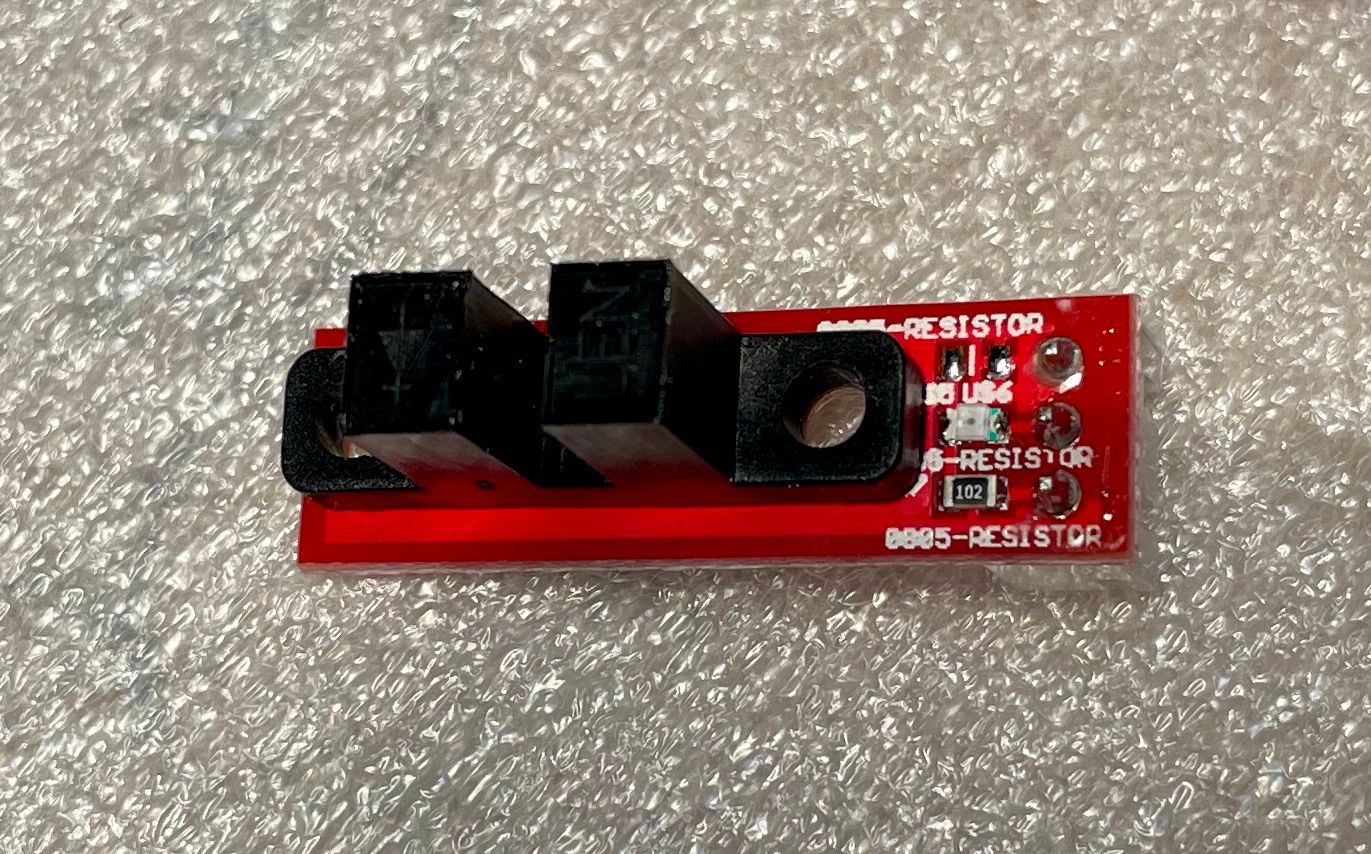
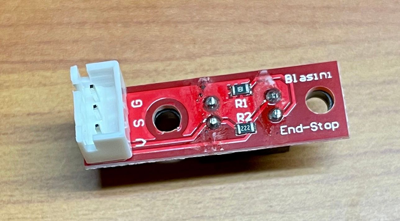
Here are two photos of the optical sensor. Not sure it is clear enough to indicate presence or absence of the pull-up or pull-down resistors.


-
@JohnOCFII
R1 is a 180 Ohm resistor in series with the emitter LED.
R2 is a 2,200 Ohm resistor to pull UP the receiver signal line.The resistor on the top is a 1,000 Ohm resistor in series with the LED on top. Is that a power-on LED?
So I would just hook it directly to the input of the Schmitt-inverter. No pull-resistors required on the input or the output of the inverter.
-
@alankilian said in Inconsistent results with optical encoder wheel filament sensor:
@JohnOCFII
R1 is a 180 Ohm resistor in series with the emitter LED.
R2 is a 2,200 Ohm resistor to pull UP the receiver signal line.The resistor on the top is a 1,000 Ohm resistor in series with the LED on top. Is that a power-on LED?
So I would just hook it directly to the input of the Schmitt-inverter. No pull-resistors required on the input or the output of the inverter.
The LED is not a power-on LED -- it lights up when the light beam is broken. Interestingly, there is a corresponding e1stop LED on the Duet board as well.
Thanks again on the advice. I'll try to wire this up tomorrow!
-
@JohnOCFII AH! I tool another look at a larger zoom level and I do see that the LED is connected between positive voltage and the output signal.
-
Progress!
I manually moved the filament back and forth a few times, just to see if I was capture what I expected to capture. Other than the fact that the signal seems inverted -- it definitely looks like the Channel 1 signal is a cleaned up version of Channel 3.
Spacing seems somewhat different too, but I can't imagine that matters in this case. I'll do a test print next.
Here's the very tiny Saleae log file: https://1drv.ms/u/s!ApuOkxTDmZEzgoHeOopsvsFwqzJ2Eck?e=6bpojT

-
Yeah, maybe that inversion does matter. The LED on the optical sensor now is behaving opposite to the sensor on the DUET e1stop.
Of course, I did buy a Schmitt trigger -inverter-...
-
OK - test print complete. I inverted the endstop in my config:
M591 D0 P7 C"!^e1stop" S0 R30:1500 L04.0 E5 A1Once again, this was just a slow vase mode test, but it looked pretty consistent. Now to do a more varied test print.
Pulse-type filament monitor on pin !e1stop, disabled, sensitivity 4.000mm/pulse, allowed movement 30% to 1500%, check every 5.0mm, measured sensitivity 4.048mm/pulse, measured minimum 92%, maximum 107% over 275.3mmHere's the Saleae capture: https://1drv.ms/u/s!ApuOkxTDmZEzgoHgcZ3MG-VMfmaWuDk?e=LBB2Ue
John