Inconsistent results with optical encoder wheel filament sensor
-
Well, this is interesting.
I moved the filament sensor from the
CONN_LCDconnection to theE1_STOPconnection. I ran a similar vase mode cylinder (no top or bottom) and my DUET M591 results were much more consistent than anything I've seen. Speed was 15mm/sec.Pulse-type filament monitor on pin e1stop, disabled, sensitivity 1.200mm/pulse, allowed movement 30% to 1500%, check every 5.0mm, measured sensitivity 4.054mm/pulse, measured minimum 28%, maximum 32% over 527.0mmI can update the L parameter to be 4 and try again.
I also captured a trace, and the Saleae still sees the messy start and end of the pulse. If these tests hold up, does that imply that the Duet RRF firmware is treating the CONN_LCD connection differently the the other endstops?
Here's a link to the Saleae capture for the above test: https://1drv.ms/u/s!ApuOkxTDmZEzgf2ue8OdskJFAV4KT9Q?e=ucEW8v
-
@JohnOCFII maybe when pin for e1stop is configured the schmitt trigger input is turned on.. or there's input buffer with schmitt trigger input on the board already... but 28-32% seems very good
-
@arhi said in Inconsistent results with optical encoder wheel filament sensor:
@JohnOCFII maybe when pin for e1stop is configured the schmitt trigger input is turned on.. or there's input buffer with schmitt trigger input on the board already... but 28-32% seems very good
Could be. Now to do a few more tests to confirm that wasn't a fluke. I'll do another vase mode test, then move on to a regular print that includes a variety of moves up to 150mm/sec. I may also try the original wheel with more, thinner spokes.
John
-
Here's a longer vase mode cylinder. Not quite as tight as the last one, but still a reasonable range, it would seem.
Pulse-type filament monitor on pin e1stop, disabled, sensitivity 4.000mm/pulse, allowed movement 30% to 1500%, check every 5.0mm, measured sensitivity 4.060mm/pulse, measured minimum 86%, maximum 109% over 1023.1mm -
@arhi said in Inconsistent results with optical encoder wheel filament sensor:
dunno that sound really bad, maybe move the connection to the
C"^e0stop"connector, dunno if it makes a difference but I'm not getting that big span on that pin
-
Sure - I can try e0stop. I'll do that tomorrow. I'd agree the result isn't great - but it was better than those results I had racing above 1000.
-
@JohnOCFII e0stop is for sure identical as e1stop
 no need to test e0stop if you are already found that e1stop will work ok
-
@arhi said in Inconsistent results with optical encoder wheel filament sensor:
@JohnOCFII e0stop is for sure identical as e1stop
 no need to test e0stop if you are already found that e1stop will work ok
Yeah, I certainly hope e1stop and e0stop are treated the same in the firmware.
Now to do more testing and see what sort of range I'll get. I'm sure as I move back to a normal profile with Z-hop, pressure advance, etc, the bounds will get larger. I figure I'll do a few more of these consistent 15mm/sec tests, perhaps with different encoder wheels, to see what range I'll get under ideal conditions. It is also worth watching the logic analyzer to see if I'm getting consistent patterns.
-
[EDIT] I got myself confused into thinking these bounces were incoming signals on this pin and tht the filter would help reduce them.
BUT the bounces are really just threshold-crossings due to a slowly-moving signal and so this filter will not improve it. It actually makes the situation worse (depending on how much is due to the LED/Receiver slowly changing and how much due to noise on the signal wire.)
So, don't listen to what I say below.
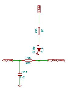
@JohnOCFII The schematic shows a lowpass filter on the E1_STOP input pin that is not on the ENC_B pin.

It's got a cutoff frequency of about 8000 Hz which would get rid of some of those bounces.
If you want to, you could try to probe one of C111 or R95 and you could see the signal that's actually getting to the micro controller.
-
Wow you've gone hard at it; it's been incredibly valuable going through the thread
I always had wide range but fairly consistent with mine; so I settled with increased tolerances and call it a day
It seems that RRF 3.2 changes the way it deals with filament sensor; could any of the changes be relevant to improving sensor accuracy?
https://github.com/Duet3D/RepRapFirmware/blob/v3-dev/WHATS_NEW_RRF3.md
-
@alankilian said in Inconsistent results with optical encoder wheel filament sensor:
[EDIT] I got myself confused into thinking these bounces were incoming signals on this pin and tht the filter would help reduce them.
BUT the bounces are really just threshold-crossings due to a slowly-moving signal and so this filter will not improve it. It actually makes the situation worse (depending on how much is due to the LED/Receiver slowly changing and how much due to noise on the signal wire.)
So, don't listen to what I say below.
So -- it might still be worth building the separate debouncing Schmitt trigger?
-
@JohnOCFII Yes, I think adding a Schimtt-Trigger would be the best way for you to get repeatable results.
Any old Schmitt-trigger input device will work for you as long as it can deal with 3.3 Volts. You don't need a fancy high-speed one.
CD40106 would work well. If you want a DIP package, here's one:
https://www.digikey.com/en/products/detail/texas-instruments/CD40106BE/376602Also, I had lunch with Otto Schmitt one time. He was an interesting fellow.
If you want help wiring it up, let me know.
-
@alankilian said in Inconsistent results with optical encoder wheel filament sensor:
@JohnOCFII Yes, I think adding a Schimtt-Trigger would be the best way for you to get repeatable results.
Any old Schmitt-trigger input device will work for you as long as it can deal with 3.3 Volts. You don't need a fancy high-speed one.
CD40106 would work well. If you want a DIP package, here's one:
https://www.digikey.com/en/products/detail/texas-instruments/CD40106BE/376602Also, I had lunch with Otto Schmitt one time. He was an interesting fellow.
If you want help wiring it up, let me know.
I'll order a couple from DigiKey. Need to think up a few others things to add to the order. It just feels weird to order something for under a dollar, than pay $8 in shipping...
I'll post my guess at wiring after looking at the datasheet and before I power up anything.
Thanks!
John
-
@JohnOCFII there's lot of things useful to have around 3d printers
- leds
- 1k resistors 1/8W
- 10k resistors 1/8W
- 1000uF 36V caps
- 3.3 - 5v and 5v - 3.3V level shifters
- switches
- connectors
- crimp terminals
- crimp plyers
- schmitt inverter circuits
- ssr's
- fet's
...
...
so see what's cheap that you know how to utilize that you can get there and make that $8 irrelevant


 ... that's how I usually go from $9 bill to $90 bill
  and ton of stuff I might use in future that I never utilize
-
@arhi said in Inconsistent results with optical encoder wheel filament sensor:
that's how I usually go from $9 bill to $90 bill and ton of stuff I might use in future that I never utilize
amen!

-
@arhi said in Inconsistent results with optical encoder wheel filament sensor:
so see what's cheap that you know how to utilize that you can get there
 and make that $8 irrelevant


 ... that's how I usually go from $9 bill to $90 bill
  and ton of stuff I might use in future that I never utilize
I wasn't quite that successful, but I did get my product amount to be twice the shipping fee.

-
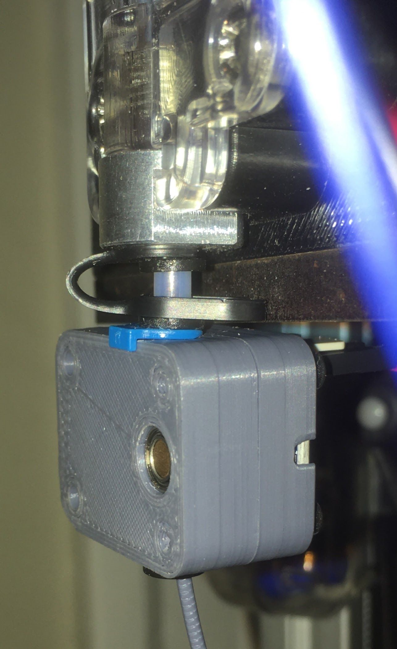
Your filament monitor travels inspired me to take the easy route and order the parts for a magnetic filament monitor from filastruder.
I printed out the case parts, did a tiny bit of scraping with a hobby knife and it's all running perfectly!
Unfortunately, I wasn't thinking and I mounted it to the bottom of the extruder because it's simple. But that means that when the extruder runs to the end of the filament and stops extruding there will be up to 3mm of extrusion missing on the print before the monitor says "No filament movement".
So I'm going to mount it above the extruder far enough so that the filament runs out at the monitor FIRST and there will be plenty to extruse for 3mm before the monitor finally says there's no filament movement.
Unfortunately, the EZStruder doesn't have a PTFE tube connector on its input-side do I'll have to hard-mount the sensor above the extruder. No big deal, but it's just something I'll have to do.
Anyway, $40 well spent in my opinion.


-
@alankilian said in Inconsistent results with optical encoder wheel filament sensor:
Your filament monitor travels inspired me to take the easy route and order the parts for a magnetic filament monitor from filastruder.
I printed out the case parts, did a tiny bit of scraping with a hobby knife and it's all running perfectly!
OK, now you are just rubbing it in.

I'm curious how that filament monitor would perform mounted further ahead of the extruder. They seem to suggest against it. On the other hand, for "filament out" basic switch sensing, the position I have (on the printer frame -- about ~350mm from the extruder) works fine. It is where I've got the optical sensor installed.
Who knows. At the end of all this I might throw in the towel and follow course, assuming the magnetic sensor would be OK on the printer frame.
-
HEY! I still have my old "Filament out" microswitch before the extruder so I can wire that directly to the magnetic movement monitor and have BOTH!
Thanks for making me look at the documentation again!
You folks are great.
Filastruder installation instructions
After the extruder:
On systems that use a bowden tube it is also possible to mount the filament monitor after the extruder. In this case filament out will not be detected until the end of the filament is in the extruder. The second two pin header on the PCB is connected a separate filament sensing switch if you want to detect filament out before the extruder, but detect movement after the extruder. -
@JohnOCFII "assuming the magnetic sensor would be OK on the printer frame."
I can't see where you have your filament monitor mounted right now.
Assuming your bowden is all tight at both ends, I think it should be possible to mount the monitor back near your spool holder.