Remounting my print bed
-
The heater is inset 25mm from the edge of the bed on all sides.
This is the front which is the single constraint:

This is the right rear which is the triple constraint:

This is the left rear which is the double constraint and the one I had the problem with creating a smooth channel. I'm hoping that mounting an U channel here will help with the issue.

-
@TLeTourneau OK, so the right rear screw is the reference, the left rear is the pitch adjuster and the front center is the roll adjuster. I see springs on all 3 screws. I assume they are there to keep the screw upright because they fit loosely in their holes. That means the entire bed plate is standing on 3 wobbly screws. That isn't going to be good for print quality.
You really want the screws to be threaded into something that will hold them tightly and prevent wobble while still allowing them to be turned for adjustment purposes. I used PTFE blocks for that. The blocks can be screwed down tightly, and using slightly undersized holes for the leveling screws will allow them to roll their threads into the PTFE. The leveling screws won't wobble, and that means the bed won't wobble. PTFE is good for this because it won't melt, no matter how hot you run the bed, and the screws can be turned easily. Nylon won't work because the friction is so high you won't be able to turn the leveling screws (I tried). There's a reason they use nylon in nylock nuts! You can find a small, inexpensive PTFE bar or block on ebay if you shop carefully and compare the price/weight of the different offerings.
This is how I mounted the screws in UMMD:
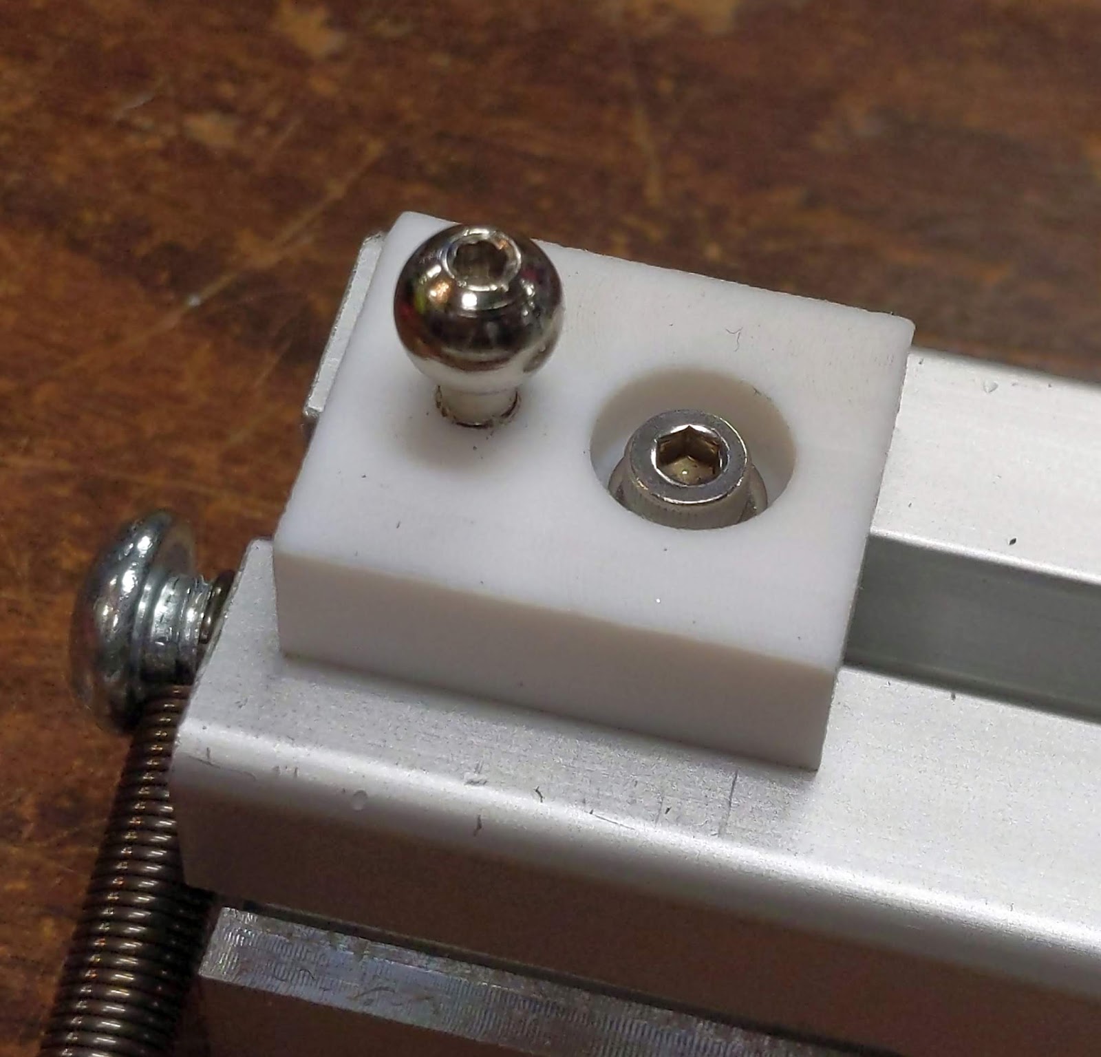
A single t-nut and screw hold the PTFE block on the t-slot, and the leveling screw threads into the PTFE. The PTFE blocks have antirotation tangs on the bottom that fit into the t-slot. If you can't cut tangs into the blocks, just mount them using 2 screws and t-nuts.
Cutting a short slot in the edge of the plate can provide the needed constraint at the pitch screw. Otherwise a short piece of C channel screwed to the bottom of the bed plate should work OK. The bed plate is only going to expand 0.5 mm or so, so you don't need a long slot for the leveling screw head to sit inside.
-
@mrehorstdmd said in Remounting my print bed:
PTFE bar or block
Yeah, I tried finding some when I built it out the first time and struck out. I'm going to give it another try. I really appreciate the responses!
-
@mrehorstdmd said in Remounting my print bed:
Nylon won't work because the friction is so high you won't be able to turn the leveling screws (I tried).
Do you think derlin would work? My brother can get derlin in the sizes that would work.
-
@mrehorstdmd said in Remounting my print bed:
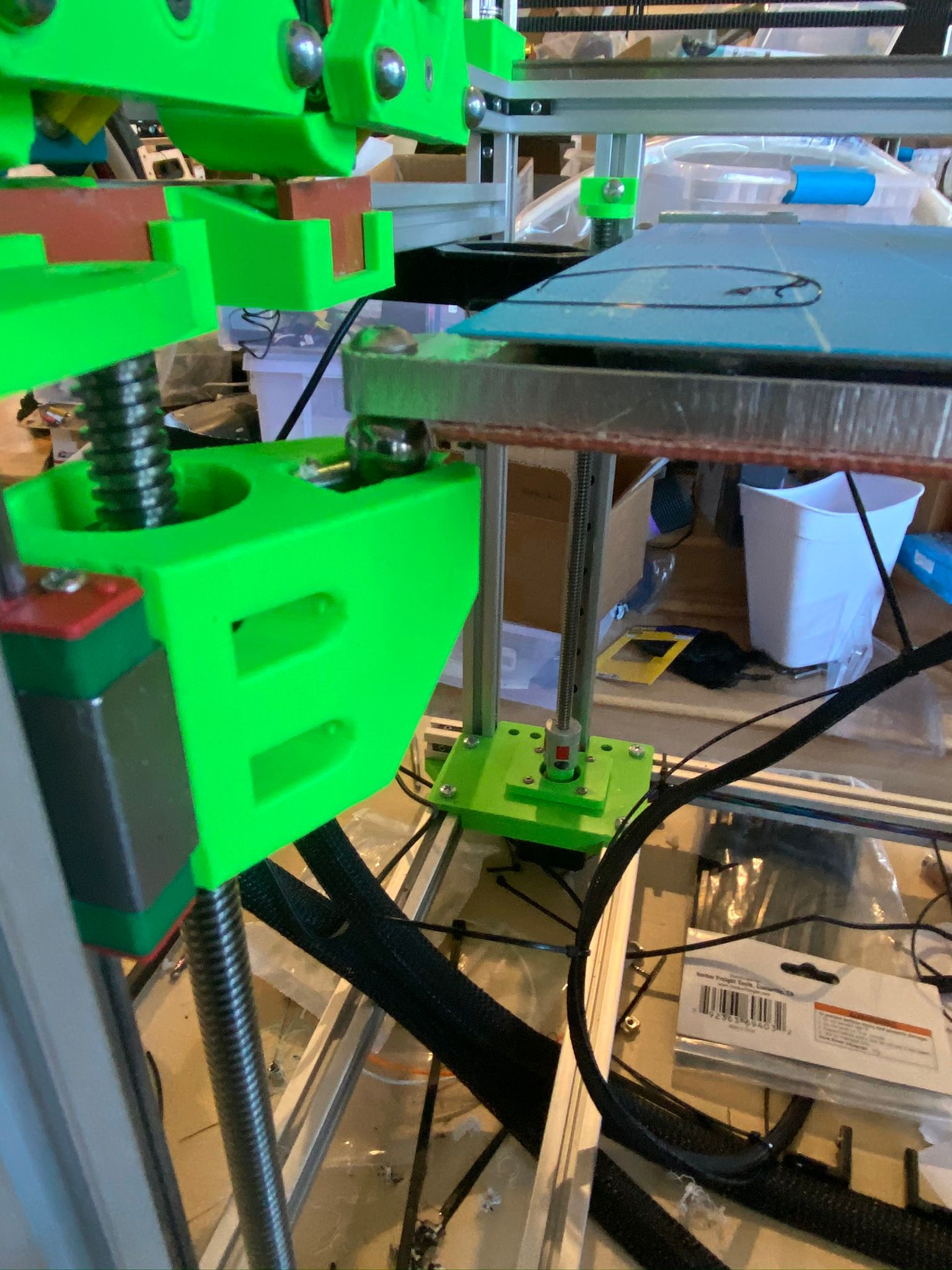
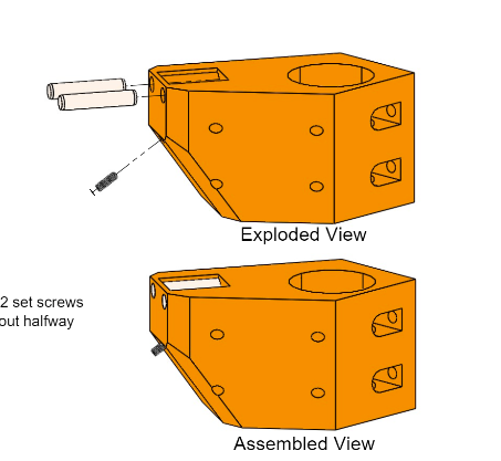
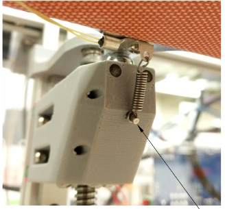
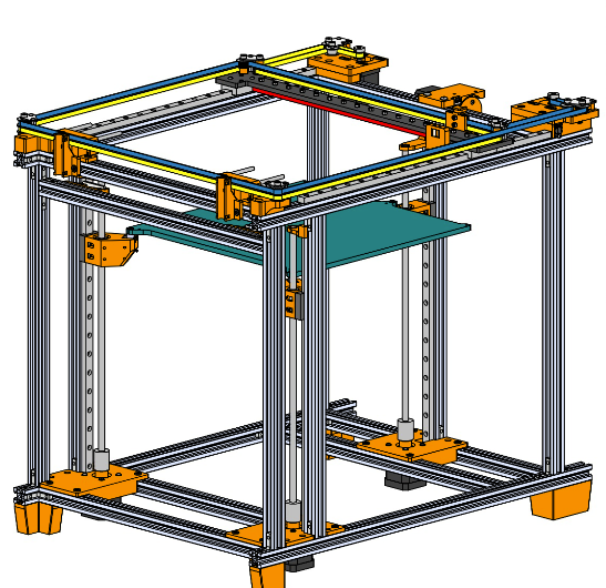
I saw someone's design that put the spherical head screws in the bed plate and put the slot for the pitch adjuster on the lifter attached to the guide rail bearing block. The slot was made from two pieces of round steel mounted in a printed plastic block. They were lifting the bed with 3 screws and using auto tramming.
Jubilee does this. Works very well.
-
-
@Danal That's the one!
-
@Danal
That is very nice, now I wish I had thought to have tabs machined into my build plate! Looking at that design I'm wondering if I'll need the 12mm linear rods. I'm going to have 3 T12x2 lead screws, 2 on the outside edges of the build plate on one side and one in the center on the other side. The build plate is attached to a relatively solid frame mode of 2020 and aluminum bar shown in the first and thirteenth posts. The aluminum bar is being replaced with a 3/8"x1-1/2" piece of 6061-T6511 aluminum bar to minimize flex.
 -
@TLeTourneau It's just aluminum. You can cut it with many types of saws, including a hack saw. Machining is not required...
-
@mrehorstdmd
Yeah but I don't want to make my print bed smaller.
-
I learned something this weekend, I'm not a machinist!
 Although I gave it a valiant effort I wasn't able to create the new side support bars for my bed out of the 1.5" x 3/8" 6061-T6511 aluminum bar. Although I had a vice on my drill press I was not able to get the holes for the lead screws and guide rods centered and square to each other on the bars. I've contacted a local machine shop and they should have them made for me in a week or two. I may put a small milling or CNC machine on my wish list for the future.