Strange Behaviour from DuetWiFi Extruder Stepper [Solved]
-
Could be a red herring but it looks like one of the board SMC components has failed.
This board is mounted upside down so its not possible for something from the power supply to fail and drip onto the duet.
I cleaned this gunk off the corner of the Driver Chip on the E0 Extruder chip but the problem still exists.
That looks like a 220 Ohm resistor next to the chip not a cap I have never seen a resistor blow like that, so I'm wondering if its come from under the Chip.
I'll have to look up the wiring of the chip and seeing if it could have been damaged by that pin.

-
looking at the pictures using 2.54mm dupont wires for the 2.00 jst ph header on the motor may not give you optimal contact as the pins are thinner as well as the spacing is different.
-
@bearer Yes I know .... but the contact was good enough and enabled me to experiment with different pin outs.
I have a 2mm pitch JST Kit turning up on Tuesday.
I am now trying to prove the E0 Driver has blown.
I have gone back to a stand Z Driver setup and stopped mapping P4 (E1) to the Z Stepper driver so I could try to use it as the default Extruder instead of P3 (E0).
Not managed to get the software to use E1 instead of E0 yet ....
Watch this space.If it all works we know its a faulty Board

-
Is this how you've wired the motor to the duet? Not super clear from the picture.
motor      duet
1 red
2          1 red
3 green    2 blue
4 blue     3 green
5          4 black
6 black
On the duet 1 & 2 should be one motor coil, and 3 & 4 the other motor coil. If you measure the resistance between red & blue, and green & black what do you get?
-
@bearer that's correct. That's how I wired it and that is correct for the Stepper Motor used for the CR10 Extruder.
However I managed to find the problem when I got exactly the same problem on the second E1 Stepper Driver .... with both the original and the new temporary cable.
While both cables passed continuity tests I examined the connectors under a microscope and Identified the problem.
Both the Old and the newly made cable had a weak pin2 connection on the Connectors provided by Duet (Blue). It was a nasty coincidence that wasted a lot of time looking for other causes! Ironically the crappy black Dupont connectors 2.5mm were more reliable than the supplied ones with the Duet.
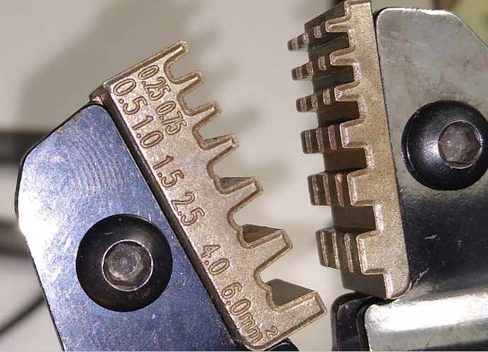
I must admit I don't like the connectors that are supplied with the Duet. I find the JST and Latch Lock Dupont connectors way more reliable and secure and the crimp pins make better contact and are stronger.It could just be they are an size my crimp tool dose not support properly;

Besides that was not the main reason the connector pins failed after 1 year.
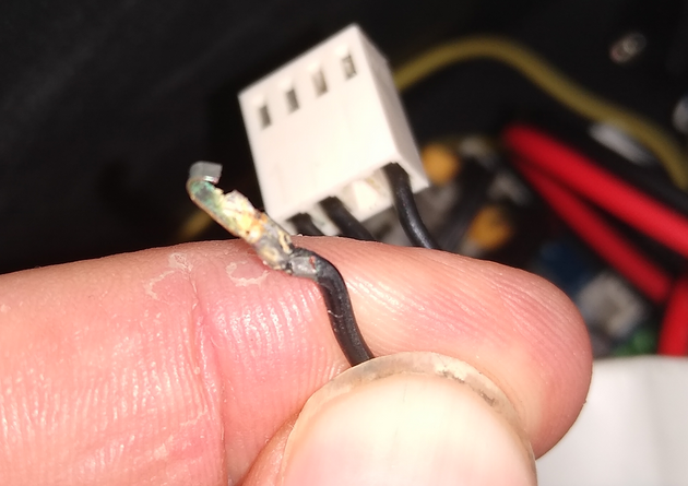
See below .... Corrosion on the original Duet Dupont Connectors I fitted 1 year ago.

This is because i find the supplied connectors from Duet ropey so I usually put a small spot of solder to hold the cable in place while I crimp it as the pin either is just a fraction too big for the slot or a fraction too small and twists in the crimp tool.
This where I think I found the root cause ..... schoolboy howler ... I borrowed the flux from a neighbour while I waited for my amazon order to arrive.
I just asked him to show it to me again ...

This is probably the reason why the pins on the Duet connectors have failed... plumbers flux must have reacted badly with the pins and caused them to corrode, weaken and break off in the plastic Dupont connector.
Doh Doh Doh!
I have just replaced all the connector pins with new ones soldered with a tiny dab of electronic PCB flux and led solder(Pb 38, Sn 60, Cu 2).
Its all working now.
... it was just really bad luck breaking the same pin on the new cable :-@
-
@simonboydfoley The flux used for plumbing and gas is usually an acid flux. It'll corrode if not cleaned.
-
@Stephen6309 yup .... I don't speak Danish where I live and I got used to not reading the label ... the irony was .... the flux label was actually written in English! :-0
What a muppet ! When I saw the corrosion that's what I immediately though had happened. I have proper flux now. I paid for being impatient and wanting to get the duet installed before all my tools in my new house had arrived.
I posted this specifically as an example for young players.
-
those tool dies look like a rough casting, not ground or edm cut, and 0.25-0.5mm^2 as the smallest die is likely too big.
it certainly won't do you any good with the 2.00mm ph connector. soldering crimped pins is asking for trouble regardless of type of flux used, and regardless of cleaning the flux after soldering.
reason i asked about the wiring is that all the chinesium steppers i've seen have had the motor coils on pins 1 & 3, and 4 & 6, or 1+2 & 4+5 and 7+8 & 10+11 for the bigger ones, so at a glance it looked a bit odd to see them out of order in yours, and the moon industries you linked to doesn't appear to be any different https://blog.moonsindustries.com/2018/12/19/how-to-connect-stepper-motor-to-your-drive/ ... but you clearly seem convinced you know what you're doing so I'll leave it at that.
edit: what he said

-
have a look at the Engineer PA-09 for crimping
-
@bearer yup I am sure the wiring is correct .... I spent a lot of pain learning that the Stepper Motors that Creality use on the Extruder are different to the ones they use on the X, Y & Z axis ...
(Looking down on the Extruder Motor);- Black
- Blue
- Green
- Red
& Reverse the direction in config
Or- Red
- Green
- Blue
- Black
Maybe this is the norm for most Motors ... I have only even used a CR10s.
Thanks for the tip ... I have ordered a new crimp tool, pricey .... but it would have been worth it to save the day I lost troubleshooting this issue, when I bent the pin on the new cable I was using to troubleshoot.
Thanks for all your help
