Multiple Motion system configuration and setup
-
@SANJR
Yes, the variables are just so you can adjust them in real time.You wouldn't be using a real endstop.
You would use a realy to "act" like an endstop.
In this way you have control over when it triggers using M42
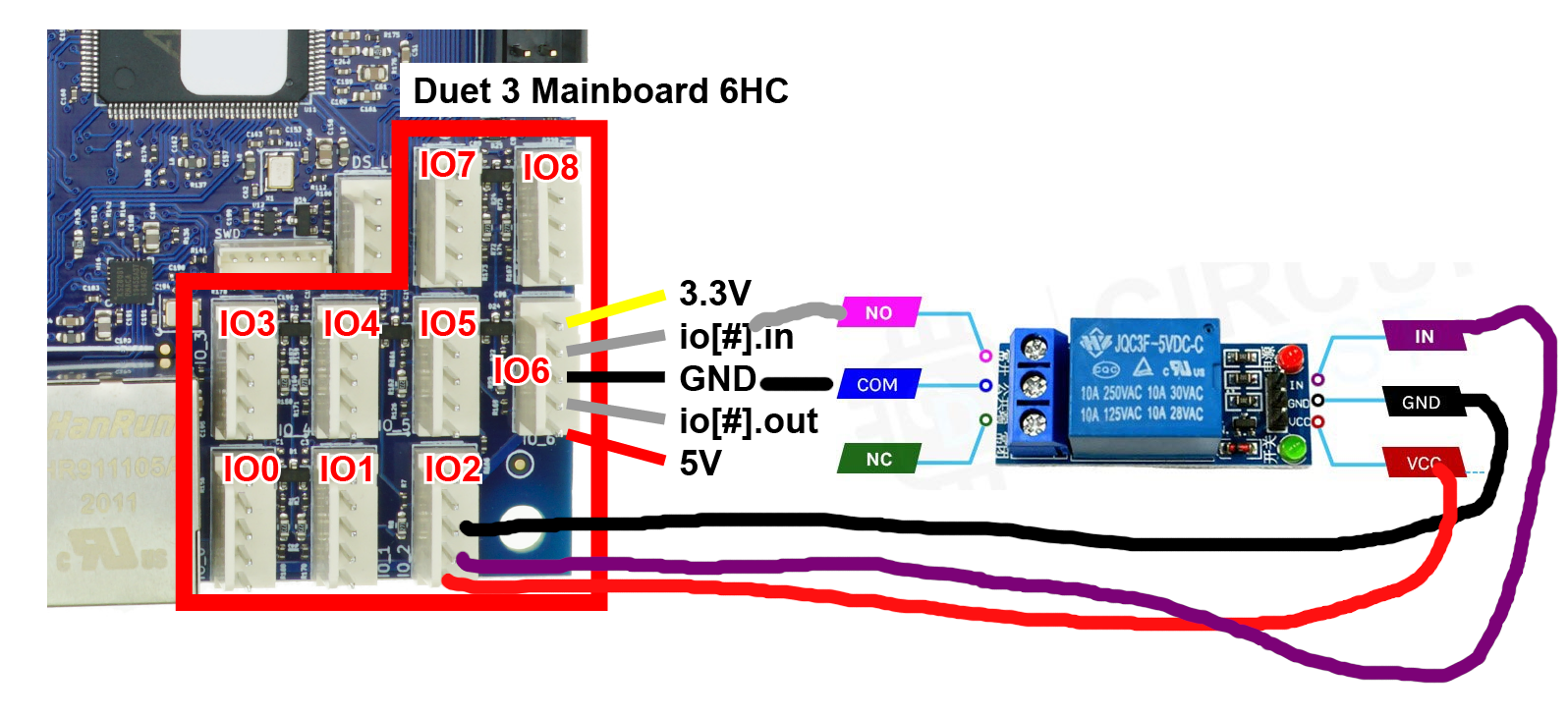
Something like this.Configure your "endstop" on IO6
M574 U2 S1 P"io6.in"; simple switch on high endConnect the wires from IO6 to the COM and NO connections of the relay.
Configure an IO output on IO2.
M950 P4 C"io2.out"Wire according to the requirements of the relay.
By sending M42 from this port, you simulate a real endstop.
So in theory you can set the axis in motion using G1 H4 and stop it any time using an M42 to close the relay (triggering the end stop)I have no idea if this will work in the way you want it to.

-
Thanks for the new sugeestion.
I will create the the required files and paste here soon. I have one constraint, since we are short of IO pins since the Z axis levelling is done with endstops and two more endstops at the maxima as tiggers to stop the out of limit travel.
So currently we have only one io pin and 3 OUT Pins empty. Is it possible to use the out pin to the relay? If not then i may have to reduce the maxima of Z axis to 1 from 2.....
And can i use any IO pins for this relay or is there any preference........
-
@SANJR
You can use any IO if it can trigger your relay.
You are better to start a new thread about the suitability of particular OUT pins.
You will need to supply details of your duet board, relay type (specifications) and how you plan to wire it. -
Thanks Owen as suggested, i am opening a new thread titled ¨Configuring stepper motor as filament feeder motor¨ for the suitability of the IO-Relay-Out PIN configuration.
Also attaching a few schmatics and codes that may suit the purpose intended.
Requesting your insights for the same plz....
-
@SANJR
My suggestion to start a new thread was specifically about whether the IO you were planning to use is suitable to drive a particular relay.
However in your new post, you have effectively duplicated this thread.
There is not really any more advice I can offer except to read the documentation in that regard.
https://docs.duet3d.com/en/How_to_guides/Wiring_your_Duet_3 -
-
There are some errors with the PintHeadState ON and PrintHeadState OFF. Error message is displayed as
M98 P¨0:/macros/Print Head State ON¨
Error: Bad command: global.PrintHeadState = 1M98 P¨0:/macros/Print Head State OFF¨
Error: Bad command: global.PrintHeadState = 0I have declared the global PrintHeadState = 0 in the config.g file before the Fans section where the OUT_6 pin is configured.
What could be the reason for the error bad command? And how to solve this issue plz......
-
-
Thanks Owen
So in the config.g file the global variable is to declared as
global PrintHeadState = 0; Assume initially offAnd in the macros to PintHeadState ON
set global.PrintHeadState = 1& in the PrintHeadState OFF
set global.PrintHeadState = 0What i mentioned above is correct?
-
@SANJR
Yes, that is correct -
Observed two strange conditions
-
After changing the syntax of the global variable. For the first few minutes, I was getting the same error message. But when i shutdown and restarted the machine after a few minutes, for the first time the motor started rotating. And when I tried to repeat it for a few more trials, the motor was not responding.
-
And during the first trial the motor did not stop when the PrintHeadState OFF macro was called. It was rotating for the U99999. So i had to force stop by pressing the emergency button in the DWC
For the first condition where the changes made to was not being updated. Is there any reason for residual voltage is being circulated due to voltage drop down....... Just a guess not sure if this the reason. How to resolve this issue plz...
Second how to control the motor U99999 stop?....
-
-
@SANJR
I can't offer any more help.
I have said all along I didn't like the way you were doing it and recommended other possibilities.
I merely offered a method that may or may not work the way you were trying to do it, but it's up to you to debug any issues.
Good luck with your project. -
I can understand
This method may not be the best way
Is there any other alternate way to get this requirement.
Only constraint which i face is the welder doesn´t have an feeder motor. It could perform in autogeneous mode (without filler wire) only. So i need to setup the feeder motor.
Previously tried a DC motor controlling them via OUT pin but i was not able to control the feed rate. But lately i learnt that a ESC can be used which helps to set the desired feedrate.
Any suggestions would be welcome please
-
This setup is completed. Hence can be closed
-
 undefined droftarts marked this topic as a question
-
 undefined droftarts has marked this topic as solved