Vectric VCarve's "Home"
-
I run a RatRig 1075 KillerBee using a Duet3 MB6HC control board (FW version 3.4.3), and Vectric VCarve as my preferred CAD program. I'm using the Ooznest post processor and a Duet CNC Pendant with buttons that can be programmed to run macros.
Within VCarve I can set the "home" position which, by default, is X0.00, Y0.00 and Z5.09mm, in relation to the work zero, i.e. 5.09mm above the starting point, and this is where the tip of the cutting tool ends up after the toolpath is complete.
But I want to change it, the reason being:
- If the job is complete, I'll need to jog away from this point to release the stock, and
- If I need to change the cutter to run the next toolpath, I need to jog away from this point to do so.
A more sensible "home" location would be more convenient, but changing these within VCarve could cause all sorts of issues as these values are relative to the work zero, not machine zero. However, I don't want to move to machine zero because I can't reach it!
So I think macros would help to resolve this, and I would like to ask if my ideas make sense:
Firstly, a macro to move the cutting tool to a safe place (say X300, Y300, Z(max)) that can either be called from the post processor (preferable) or assigned to a macro button on the controller, and a second macro to bring the spindle to the front and centre of the machine, if I want to change the cutting tool. I appreciate I will need to reset the Z height after doing this bit, but automating that is the next step!
Thanks
-
@nightowl Yes. It makes sense to write some macros.
You can define the "start.g" and "end.g" macros in the sys folder , which are automatically called at start / end of your job. -
Thank you, @cosmowave
-
@nightowl The first thing I did was create a macro file named: Globals.g that contains all of the 'global' values that might change, such as where work home goes. It gets called at the beginning of my config.g and then if anything changes in the hardware (like I physically move an endstop) I just update the global value.
The lines in config.g->; load the macro \ M98 P"0:/macros/Globals.g"so, this is a few lines from my Globals.g to establish where my Z-setter lives. If it moves I just changes these lines ->
; where the Z setter center is
global ZSetXPos = 190
global ZSetYPos = 19
and then I have a macro file named ToZSetter.g like this:
G53 G0 X{global.ZSetXPos} Y{global.ZSetYPos}mark
-
As I understand it, you've used a macro, called from the config.g file, that sets a number of variables. I can certainly see the benefit of that, primarily as any future changes would only need to be made in the globals.g file, without messing with config.g.
Using an end.g macro @cosmowave refers to will certainly resolve moving the spindle to a safe area, once the toolpath is complete. I've already written a macro that moves the spindle to a safe point when I pause the cut, so I would use the same co-ordinates in the end.g macro. The only (slightly) annoying thing is that the move to X0.00, Y0.00, Z5.00 from the post processor, would still happen, so I will need to look at the PP and, maybe, call end.g from there, instead.
I'm still struggling to get my head around re-setting the Z height when I change the cutting tool, but this is a legacy from my previous machine. My Shapeoko had a BitZero and a BitSetter. The BitZero was used to find the corner of the workpiece and/or the initial Z height of the stock. The BitSetter process was only initialised if a cutting tool change was required within the project. Essentially, this measured new tool length, compared it to the original tool length and then adjusted the Z height accordingly.
I'm still using the paper method to get the initial Z height and manually clicking "Set Work XYZ" button (I eventually want to automate this, but it's not a priority) but I would like to automate the Z height adjustment (initiated using a macro) as a slightly higher priority.
Or maybe I'm overthinking this..?
-
@Nightowl Yes, exactly. When things physically get repositioned I just have to update the Globals.g file and all my macros keep working as is.
Yes, I usually have vcarve just end up somewhere safe (like 20,20,50 with 25mm stock) and then I run a macro or a simple G1 to push the head out of the way.
As for the BitSetter thing I'm not sure what you're missing now that you had. The paper method?
My milling machine uses a Z probe at a fixed location and so there's a macro to move the head to the button center, drop and touch the button to detect bit height (it actually sets work zero). I change bits, click the macro, wait for the machine. My CNC uses a puck and so I skip the first line but manually center the puck.
This assumes the head is at a safe height (!) and it sets work coord space 2 - which is what I use for jobs. It's this->
G53 G0 X{global.TouchX} Y{global.TouchY}
G30 S-1			; lower z until the metal probe is hit
G10 L20 P2 Z{global.TouchZ}	; Z = 0 + puck height in second coord system
G1 Z38 F600		; raise z 1.5 inch
You can start the macro with a G53 G0 Z{global.SafeZ} for whatever the safe Z is in machine coords.
-
@markz said in Vectric VCarve's "Home":
Yes, I usually have vcarve just end up somewhere safe (like 20,20,50 with 25mm stock) and then I run a macro or a simple G1 to push the head out of the way.
I understand this, but it is at the mercy of the stock height. It's because Vectric uses this, rather than machine co-ordinates, I'd prefer to go down the macro route. To be honest, this is just in case I forget to take account of the stock height

@markz said in Vectric VCarve's "Home":
As for the BitSetter thing I'm not sure what you're missing now that you had. The paper method?
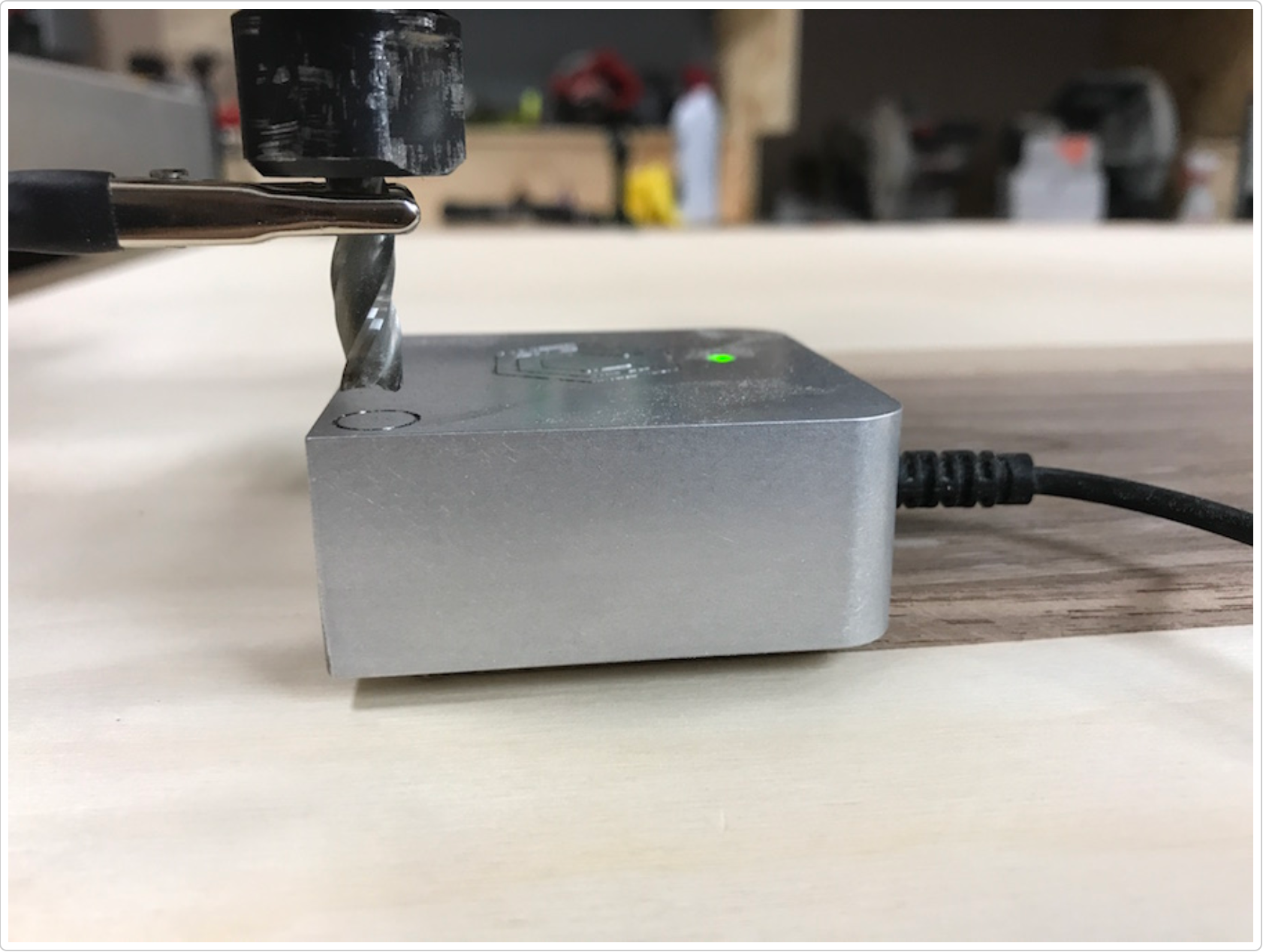
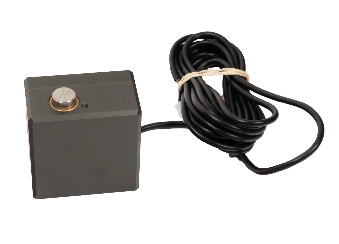
No. The BitSetter is probably the equivalent to your "button" to detect the bit height. If the code is as simple as you've shown above, maybe it is much easier than I thought. Does your Z Probe have a "puck" and a "button", or are they separate? If they are, I think the puck is equivalent to the BitZero and the button to the BitSetter, shown below:
BitZero:

Using this, I would have to remember to clip the crocodile clip to the cutting tool, or it would drive right through the BitZero when it measures the Z height! I would also need to know how to connect this to the Duet
BitSetter:

I already have the BitZero, which is normally used to determine the X0, Y0 and Z0 of the stock, but I would need to understand how it works before I start working on that macro, hence using the paper-and-eye method. I like the BitSetter too, but it's $120 (plus shipping and import taxes to the UK) and it fits to the front of a Shapeoko. I'm hoping to make one to fit within the baseboard of my CNC machine.
Thanks for the macro code. This will certainly help

-
@Nightowl Yes, on my milling machine I have a home-made bitsetter. It's screwed down and at a semi-fixed location. Everything I mill is referenced off the table. The macro, at the simplest level, is just a G30 along with a Zprobe definition that uses an input pin on/off. The milling machine head (and bit) are at ground and the fixture plate is clipped to the sense pin.

On my CNC I use a BitZero equivalent (that came with it) that's an aluminum puck with a wire to the controller sense pin. Here, too, the head is at ground. Since I set the puck down (usually on the bed, rarely on the stock) I use a shorter macro without the moveto X,Y start but otherwise it's the same G30 thing and the puck is a Zprobe. If I'm doing a job with tool changes I just leave the puck in one place and set the XY vars.
As for how to end the job with VCarve, mainly I ignore the ending move as long it's above the stock. If you want to lazy it - edit the postprocessor to have it always call your movetosafe macro - I think you can just put the M98 call in the FOOTER section.
-
@Nightowl So, I'm including my custom postprocessor for you to take a look at. Since RRF is so good at arcs it enables them fully. The spindle control is for my CNC.
Anyway, note that the FOOTER section is three lines:
M5 - turn off spindle
G0 [ZH] - go to home z
GO [XH][YH] - go to home xyif you comment out the last two lines it will not home at the end and you can instead do what you will.
+================================================ + + Grbl - Vectric machine output configuration file + +================================================ + + History + + Who When What + ======== ========== =========================== + MarkZ 12/25/2020 Customized to Duet3d RRF 3 + ======== ========== =========================== POST_NAME = "Duet3d RRF Arcs (mm) (*.gcode)" FILE_EXTENSION = "gcode" UNITS = "MM" DIRECT_OUTPUT = "VTransfer" +------------------------------------------------ + Line terminating characters +------------------------------------------------ LINE_ENDING = "[13][10]" +------------------------------------------------ + Block numbering +------------------------------------------------ LINE_NUMBER_START = 0 LINE_NUMBER_INCREMENT = 10 LINE_NUMBER_MAXIMUM = 999999 +================================================ + Formatting for variables +================================================ VAR LINE_NUMBER = [N|A|N|1.0] VAR POWER = [P|C|S|1.0|10.0] VAR SPINDLE_SPEED = [S|A|S|1.0] VAR FEED_RATE = [F|C|F|1.1] VAR X_POSITION = [X|C|X|1.3] VAR Y_POSITION = [Y|C|Y|1.3] VAR Z_POSITION = [Z|C|Z|1.3] VAR ARC_CENTRE_I_INC_POSITION = [I|A|I|1.3] VAR ARC_CENTRE_J_INC_POSITION = [J|A|J|1.3] VAR X_HOME_POSITION = [XH|A|X|1.3] VAR Y_HOME_POSITION = [YH|A|Y|1.3] VAR Z_HOME_POSITION = [ZH|A|Z|1.3] +================================================ + Block definitions for toolpath output +================================================ +--------------------------------------------------- + Commands output at the start of the file +--------------------------------------------------- begin HEADER "m117 [39][91]Duet3d RepRapFirmware v3 VCarve post processor [93][39]" " " "m117 [39][91]FILENAME: [TP_FILENAME][93][39]" "m117 [39][91][TIME], [DATE][93][39]" " " "m117 [39][91]MATERIAL size: [XLENGTH][34] x [YLENGTH][34] x [ZLENGTH][34][93][39]" "m117 [39][91]Z Zero Position: [Z_ORIGIN][93][39]" " " "m117 [39][91][TOOLNAME][93]" " " "m117 [39][91] SET SPINDLE SPEED RPM [93][39]" " " "m117 [39][91]TOOLPATH NAME: [TOOLPATH_NAME][93][39]" "T0" "G21" "G90" "G0[ZH]" "G0[XH][YH]" +--------------------------------------------------- + Command output after the header to switch spindle on +--------------------------------------------------- begin SPINDLE_ON "M3 P0 [S]" "G4 S4" +--------------------------------------------------- + Commands output for rapid moves +--------------------------------------------------- begin RAPID_MOVE "G0[X][Y][Z]" +--------------------------------------------------- + Commands output for the first feed rate move +--------------------------------------------------- begin FIRST_FEED_MOVE "G1[X][Y][Z][P][F]" +--------------------------------------------------- + Commands output for feed rate moves +--------------------------------------------------- begin FEED_MOVE "G1[X][Y][Z][P]" +--------------------------------------------------- + Commands output for the first clockwise arc move +--------------------------------------------------- begin FIRST_CW_ARC_MOVE "G2[X][Y][I][J][F][P]" +--------------------------------------------------- + Commands output for clockwise arc move +--------------------------------------------------- begin CW_ARC_MOVE "G2[X][Y][I][J]" +--------------------------------------------------- + Commands output for the first counterclockwise arc move +--------------------------------------------------- begin FIRST_CCW_ARC_MOVE "G3[X][Y][I][J][F][P]" +--------------------------------------------------- + Commands output for counterclockwise arc move +--------------------------------------------------- begin CCW_ARC_MOVE "G3[X][Y][I][J]" +--------------------------------------------------- + Commands output at the end of the file +--------------------------------------------------- begin FOOTER "M5" "G0[ZH]" "G0[XH][YH]" -
That's great information, thank you @markz
I would comment out the last two lines and then add a line to run the end.g macro, to send the spindle to its safe position, then.
I imagine this should work:
+---------------------------------------------------
+  Commands output at the end of the file
+---------------------------------------------------

begin FOOTER

"M5"
+-- "G0[ZH]"
+-- "G0[XH][YH]"
"M98 P"end.g""
With the end.g macro looking something like this:
; end.g
G1 Z{max(move.axes[2].userPosition+5,move.axes[2].max-5)} F2400	; move the Z axis to a safe height
G0 X273.5 Y560							; move XY to a safe place
I'm still working on the probe macro...