Accelerometer Installation Help / Search Inspiration
-
Hello,
I ordered 2 LIS3DSH acceleration sensors today.
Name: LIS3DSH 3-Axis Accelerometer MEMS Sensor Arduino ESP8266 STMI would like to install it permanently and, if necessary, connect it with a USB cable, for example.
One sensor comes as close as possible to the print nozzle and the other sensor should be installed under the print bed.I have the Duet 2 Wifi board with PT100 daughter board.
I would like to lay the cables in such a way that there is a built-in USB socket on the outside of the printer housing, which is firmly connected to the Duet 2 Wifi.
A USB built-in socket should also be installed on the print bed and also on the print head.If I now want to determine the acceleration values from the print bed or the print head, I connect the sensors using a USB cable.
At least that's my current plan.
How did you solve it with your printer?
Do USB cables work for this purpose?
Is there a more elegant solution?
Please post photos if possible, so you not only help me, but also other users who are planning the same thing and want to be inspired.Thank you in advance

Google Translate from German to English
------------ Original Text -------------
Hallo,
ich habe mir heute 2 LIS3DSH Beschleunigungssensoren bestellt.
Bezeichnung: LIS3DSH 3 Achsen Beschleunigungs Accelerometer MEMS Sensor Arduino ESP8266 STMIch möchte sie fest einbauen und bei Bedarf zB mit einem USB Kabel verbinden.
Einen Sensor kommt so nah wie möglich an die Druckdüse und der andere Sensor soll unter das Druckbett verbaut werden.Ich habe das Duet 2 Wifi Board mit PT100 Tochterplatine.
Die Kabel möchte ich so verlegen dass außen am Drucker-Gehäuse eine Einbau USB Steckdose ist, die mit dem Duet 2 Wifi fest verbunden ist.
An dem Druckbett und auch am Druckkopf soll ebenfalls eine USB Einbaubuchse verbaut sein.Wenn ich jetzt die Beschleunigungswerte vom Druckbett oder dem Druckkopf ermitteln möchte, verbinde ich die Sensoren mittels USB Kabel.
So ist zumindest mein derzeitiger Plan.
Wie habt ihr es bei Eurem Drucker gelöst ?
Funktionieren USB Kabel für diesen Zweck ?
Gibt es eine elegantere Lösung ?
Postet bitte Fotos wenn möglich, damit helft ihr nicht nur mir, sondern auch anderen Usern die das gleiche vorhaben und sich inspirieren lassen möchten.Vielen Dank im voraus

-
Hello,
I just received my accelerometers and had the exact same idea, so I wanted to check if you (or anyone else) tried this?
Soldering usb 3.0 connectors to both ends (maybe even usb-c female) and using a standard USB 3.0 cable (or usb-c cable) seems like a very convenient idea, but before going into too much trouble of doing everything, I just wanted to check if anyone tried it. It would be quite a waste of time to do all that if it does not work.
Any input appreciated.
thanks!
-
@omni
I initially had problems wiring the sensor correctly because I have a PT100 daughter board and two cables are swapped there.
Here is my Thread on the topic of cabling.I haven't got around to installing the USB3 plugs yet.
I wanted to do that if I wanted to convert my printer from linear rails to round rods (12mm) in the near future.
Then some changes are made to the print head, such as replacing the BLTouch with a self-made level sensor.
The BLTouch delivers false values if you have a magnetic print bed.
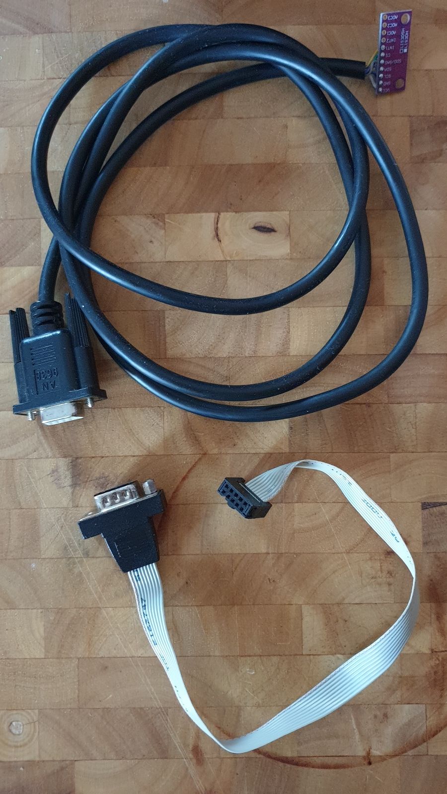
The IR probe will remain my main sensor, but on some surfaces it also delivers incorrect values, for example when printing on glass or on very rough surfaces.First I tried to connect the Accelerometer with a serial 9pin cable.
The short piece of cable should be installed in the printer.
Unfortunately, this type of cable does not work.

Currently I have connected the Accelerometer with a USB3 cable without a connector in between.
This works perfectly.
I soldered the CS line, which is very susceptible to interference, to two lines that are twisted and have their own shielding in the USB3 cable.
You should pay attention to that.If the conversion of my printer is pending, then I will build USB3 plugs in between to be able to connect the two acceleration sensors individually later.
I had ordered two LIS3DSH sensors... two LIS3DH sensors were delivered.
They refunded the purchase price and I was allowed to keep the sensors.
So I use it now, because thousands of other users get along with it too.
Google Translate
----- Original Text -----Ich hatte erst Probleme den Sensor richtig zu verdrahten, da ich eine PT100 Tochterplatine habe und dort werden zwei Kabel vertauscht.
Hier geht es zu dem Tread von mir zu dem Thema Verkabelung.Ich bin noch nicht dazu gekommen mir die USB3 Stecker fest einzubauen.
Das wollte ich erledigen wenn ich demnächst meinen Drucker von Linearschienen zu Rundstäben (12mm) umbauen möchte.
Dann werden einige Änderungen am Druckkopf vorgenommen wie zum Beispiel wird der BLTouch durch ein selbst gebauten Levelsensor ersetzt.
Der BLTouch liefert verfälschte Werte wenn man ein magnetisches Druckbett hat.
Der IR-Probe wird weiterhin mein Hauptsensor bleiben, aber bei manchen Untergründen liefert auch er verfälschte Werte, zum Beispiel wenn man auf Glas druckt oder auf sehr rauen Oberflächen.Zuerst hatte ich versucht den Beschleunigungssensor mit einem Seriellen 9Pin Kabel zu verbinden.
Das kurze Stück Kabel sollte im Drucker verbaut werden.
Aber diese Art von Kabel funktioniert leider nicht.
(Siehe Foto oben)Momentan habe ich dem Beschleunigungssensor mit einem USB3 Kabel verbunden ohne Stecker dazwischen.
Das funktioniert perfekt.
Die CS Leitung die sehr anfällig für Störungen ist, habe ich mit zwei Leitungen verlötet die in sich gedrillt sind und eine eigene Abschirmung im USB3 Kabel haben.
Darauf sollte man achten.Wenn der Umbau meines Druckers ansteht, dann werde ich USB3 Stecker dazwischen bauen um später die beiden Beschleunigungssensoren einzeln anstecken zu können.
Ich hatte mir zwei LIS3DSH Sensoren bestellt... geliefert wurden zwei LIS3DH Sensoren.
Sie haben mir den Kaufpreis zurück erstattet und die Sensoren durfte ich behalten.
Also nutze ich jetzt diese, denn tausende von anderen Anwendern kommen damit auch zurecht.
-
@norder
Hi my friend.Thanks so much for the detailed answer.
Same situation here, hahaaha! I ordered two LIS3DSH from ebay - got two LIS3DH..... obviously they don't have LIS3DSH at all, they are just claiming they do. I asked some sellers on Aliexpress claiming to sell LIS3DSH - but none of them actually do, it's all LIS3DH.My first try was going to be the flat cable with the IDC - 10 pin connector on the DUET side and 2.54 mm- 10pin connector on the accelerometer side, but trying to keep the "CS" wire away from the others.... That is the easiest to try out. But if that does not work, I will go the USB 3.0 cable route.....
Thanks again!
-
@omni said in Accelerometer Installation Help / Search Inspiration:
... I ordered two LIS3DSH from ebay - got two LIS3DH..... obviously they don't have LIS3DSH at all, they are just claiming they do. I asked some sellers on Aliexpress claiming to sell LIS3DSH - but none of them actually do, it's all LIS3DH...
The world is bad.

I sent a photo to the seller as proof, showing that the sensor had already been unpacked and soldered, and as an explanation that I only then read from the imprint on the back of the board that it was not the part I ordered acts.
I was then offered a replacement or a refund.
I then decided to have the correct sensors replaced, but the next day I received an email that the full purchase price was refunded to me.
They probably didn't have a replacement they could send me !?
I kept the IDC 10pin Socket.
First I tried to insert the cables as you should, but some of these cutting pins in the connector were bent because some cables were too thick.
I then bent all the contacts outwards and soldered the cables and then covered the connector and a piece of the cable with hot glue and shaped it nicely.
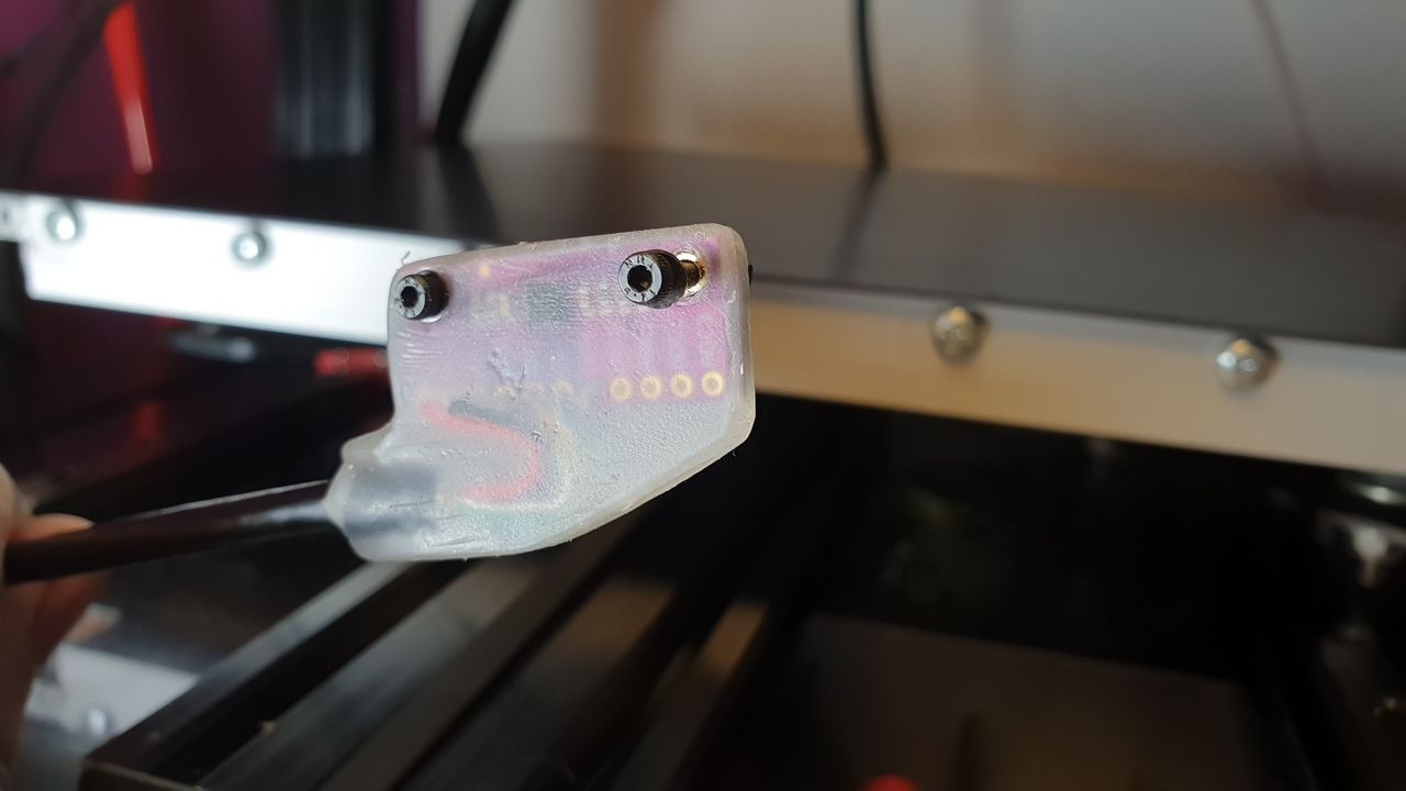
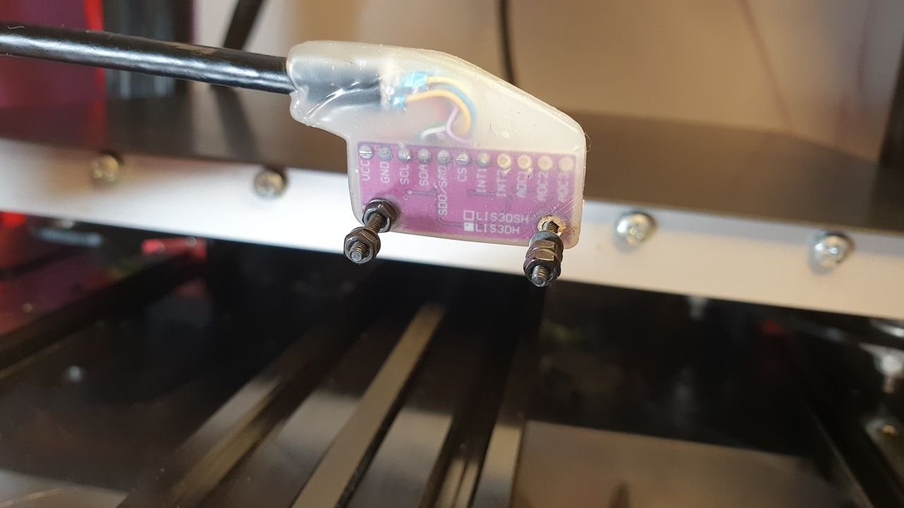
I also cast one of the two sensors (which is currently permanently connected) in hot glue.
Two brass tubes are inserted in the holes so that the circuit board and the hot glue are not squeezed.

Later, during the major conversion, it is installed under the print bed and a USB3 socket is mounted on the side of the print bed.Google Translate
----- Original Text -----Die Welt ist schlecht.

Ich habe ein Foto als Beweis zum Anbieter geschickt, wo zu sehen war dass der Sensor bereits ausgepackt und verlötet wurde und als Erklärung das ich erst dann anhand des Aufdruck auf der Rückseite des Boards, gelesen habe das es sich nicht um das von mir bestellte Teil handelt.
Daraufhin wurde mir eine Ersatzlieferung angeboten oder eben eine Rückerstattung.
Ich hatte mich dann für die Ersatzlieferung der richtigen Sensoren entschieden, aber am nächsten Tag kam eine E-Mail das mir der komplette Kaufpreis zurück erstattet wurde.
Die hatten wohl keinen Ersatzlieferung die sie mir schicken konnten !?
Die IDC 10Pin Buchse habe ich behalten.
Erst habe ich versucht die Kabel so einzusetzen wie man es machen sollte, aber dabei sind mir einige dieser Schneide-Pins im Stecker verbogen weil einige Kabel zu dick waren.
Ich habe dann die ganzen Kontakte nach außen gebogen und die Kabel verlötet und anschließend den Stecker und ein Stück des Kabels mit Heißkleber überzogen und schön in Form gebracht.
Einen der beiden Sensoren (der zur Zeit permanent angeschlossen ist) habe ich auch in Heißkleber gegossen.(Bilder siehe oben)
Es sind in den Bohrungen zwei Messingröhrchen eingesetzt damit die Platine und der Heißkleber nicht gequetscht werden.Später beim großen Umbau wird der unters Druckbett verbaut und eine USB3 Buchse an die Seite des Druckbettes montiert.
-
Tja, dass mit der Falschlieferung ist mir auch passiert. Das machne die Chinamänner wohl gerne.
Der Ausbau mit dem Flachbandkabel und dem Sub-9 Stecker, wie du hier zeigst, habe genauso gemacht!
Tja, wenn ich der 1. Lauf starte klapp es oftmals und ich kann Daten sammeln. In den späteren versuchen
kommt dann der "HeatTaskStuck"-Fehler.Ich finde es recht witzig, dass es erst geht und später nicht mehr. Bist du der Meinung, das es mit einem USB-Kabel getan ist?
Viele Grüße
Sebastian
-
@dk4ya
Since the CS channel is very susceptible to interference, it can very well be that the cable is the cause of the error in your case.
Switching to a USB3 cable is not a big deal unless you have to buy/order it first.
If you are a little bit enthusiastic about technology, then you often have a USB3 cable which you can misuse for this purpose.
I would swap the cables.
Make sure that the CS channel gets its own shielded wire in the USB3 cable.Please let us know if replacing the cable helped.
It can be helpful to other users. Thanks.Google Translate
--- Original Text ---Moin Sebastian,
da der CS Kanal sehr störanfällig ist, kann es sehr gut sein dass das Kabel bei Dir die Ursache für den Fehler ist.
Auf ein USB3 Kabel zu wechseln ist kein großes Ding, wenn man es sich nicht erst kaufen / bestellen muss.
Wenn man etwas Technikbegeistert ist, dann hat man oft ein USB3 Kabel welches man hierfür Zweckentfremden kann.
Ich würde die Kabel tauschen.
Achte darauf das der CS Kanal seine eigene abgeschirmte Leitung im USB3 Kabel bekommt.Berichte bitte ob der Kabeltausch geholfen hat.
Es kann andere User behilflich sein. Danke.