Battling sources of vibration and noise
-
@engikeneer That's a creative idea, I'll keep that in mind.
For now I just finished designing a revised bracket similar to what I had originally. It has gotten quite a bit wider to accommodate the two dampers but there is width-space available. Since doing the enclosure stuff I actually don't have a working printer at the moment so I'll get that sorted out first and we'll see from there.

-
The shear loading on the rubber you have in that bracket seems less than optimal.
Personally I'd be trying for something in-line similar to @Kolbi 's suggestion.
And @engikeneer 's suggestion of o-rings seems like both the easiest and best...I'd use a larger OD bearing (any specific reason you used needle bearings?), and use some nice fat silicone o-rings. That way you are not putting shear load on the soft material.
Easy to modify your new bracket to get that too.
-
@theruttmeister said in Battling sources of vibration and noise:
The shear loading on the rubber you have in that bracket seems less than optimal.
At the time you made your post, I was already printing the first bracket in this style. So I tried it out and you are definitely right, shear loads are not idea and in this case the loads were to large, causing unacceptable deflection.
Personally I'd be trying for something in-line similar to @Kolbi 's suggestion.
There are a couple difficulties I see with the soft dog-bone style. One, if you make to linkages, they need to be absolute same length, even under load. Otherwise the axle sits at an angle, in turn causing belt tracking problems. Two, I don't really have a good way of making rubber-ish shapes like that (except for printing them in tpu maybe), nor do I have a good source for rubber material that thick. Finally, and maybe most important of the three. If I understand the design correctly, you have a rigid bracket locating the bearings and that bracket is decoupled using the rubber-ish dog-bone links. This still allows for the bracket to vibrate and I believe that the bracket itself is emitting noise, not just coupling it further down the frame.
And @engikeneer 's suggestion of o-rings seems like both the easiest and best...
I agree, yet I had trouble sourcing o-rings (round or ideally square) in the size I need, especially the thickness proves to be and issue. And I am not a fan of doubling or even tripling up on thinner o-rings, because keeping them in place reliable becomes more difficult I think.
In the end I did more or less go the o-ring approach though
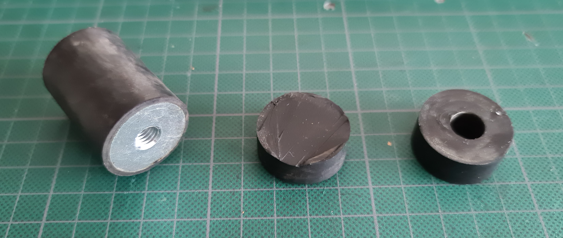
 I got myself some more of the type e dampers and cut them into pucks the thickness I need. Then I constructed a diy cork borer by sharpening a piece of metal tubing and printing an adapter so I could chuck in my drill. I used that device to drill the center holes, where the bearings sit and it worked surprisingly well.

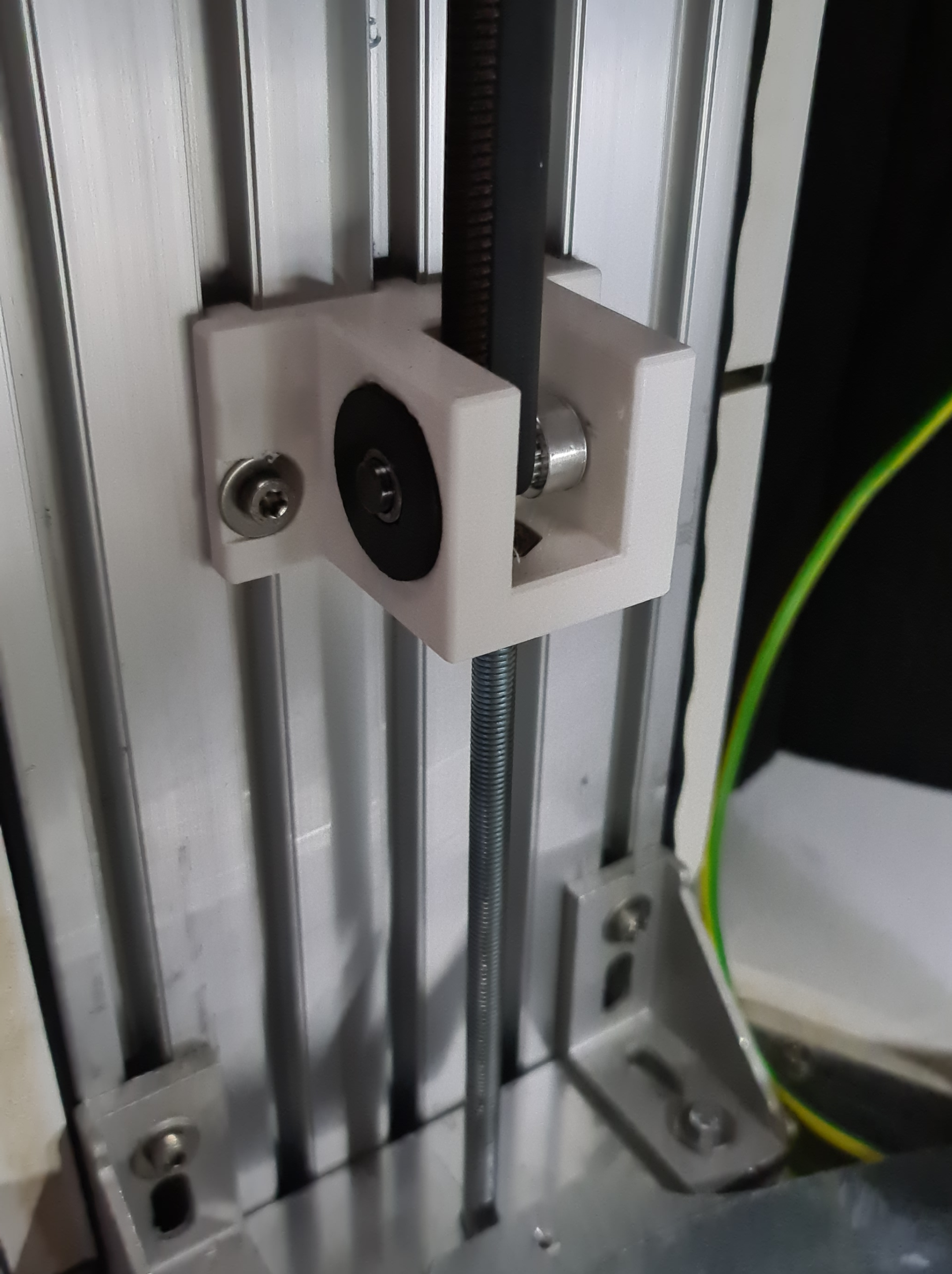
After some more bracket redesigning I ended up with this. It's fairly compact, easy to install and tension and does what it is supposed to do.

This upgrade brought the noise levels down low enough that you can still hear the machine running on some moves from the next room if it is really quiet. So not perfect but we are definitely getting closer and closer. The next thing I have planned is to redesign the motor brackets to use this style of rubber washers as well. Even tough I have stated before that the upper bearing are not in play. I have some other changes I want to do to the brackets so why not squish the o-rings in there as well right.
-

I've seen a setup like this on a bio-chemistry machine. High precision, zero noise, a lot of speed. The difference is that it used woven nylon belts, ones like you would have as a seatbelt, instead of rubber. They stretch almost not at all but dampen the noise.
-
Your new bracket was exactly what I was imagining!
Although having access to McMaster, I would have probably used something like this:

@arhi
Interesting...
I imagine they allow the belt to vibrate, dissipating the energy, but not conduct it into something that makes unpleasant noises if it vibrates.
Clever use of two wildly different stiffness materials (the belts being much less stiff than 2 inch webbing). -
@arhi Always interesting to hear how they tackle similar issues in 'the big leagues'. I am not sure I see how nylon belts would dampen vibrations, but hey the ones who build machines like that are not the ones who starting threads on struggling with the issue

@theruttmeister Living in Belgium, McMaster is sadly not really an option for me

-
@Nxt-1 said in Battling sources of vibration and noise:
issues in 'the big leagues'
I saw many things in the "industry" / "big leagues" wrt belts that made very little sense to me. This "webbing" (that's the proper term for that seatbelt like strip?) is something I have seen a lot as pulley holders. OTOH a proper pillow blocks, fixed bearings and elastic link between motor and the rest of the machine is the main element "big leagues" use that we don't normally see on our printers. It both inprove precision big time and reduces noise. It increases compexity as you get to have 2 belts instead of one, or you get belt+leadscrew instead of just leadscrew, but the difference is significant
-
@arhi said in Battling sources of vibration and noise:
webbing
its what its refered to in more outdoorsy settings at least
-
@bearer said in Battling sources of vibration and noise:
@arhi said in Battling sources of vibration and noise:
webbing
its what its refered to in more outdoorsy settings at least
I watched adam savage make his new apron last night and he was referring to that strip as webbing so that + theruttmeister calling it webbing makes me assume that's the "common term"
 To be honest I don't even know the local term fot that strip
-
@arhi said in Battling sources of vibration and noise:
a proper pillow blocks, fixed bearings and elastic link between motor and the rest of the machine is the main element "big leagues" use that we don't normally see on our printers.
Can you elaborate, I interpret this as a motor with a pulley on its shaft. Connected with an elastic belt? to a second shaft that is supported by these pillow blocks. And from there a second belt (or just the shaft depending on the application) to output the power to wherever it's needed?
-
@Nxt-1 said in Battling sources of vibration and noise:
@arhi said in Battling sources of vibration and noise:
a proper pillow blocks, fixed bearings and elastic link between motor and the rest of the machine is the main element "big leagues" use that we don't normally see on our printers.
Can you elaborate, I interpret this as a motor with a pulley on its shaft. Connected with an elastic belt? to a second shaft that is supported by these pillow blocks. And from there a second belt (or just the shaft depending on the application) to output the power to wherever it's needed?
sorry that was not related to this webbing thing ..
the usual setup on these big expensive machines is
steel frame
on top of steel frame are 2 pillow blocks supporting the threaded rod
sometimes between pillow block and steel frame there is some "plastic" ~1-2mm thick plate (dunno what material it is but feels like plastic). One one side of the rod pillow block is "blind", on other side of the rod, rod protrudes from the pillow block, and have a pulley. Then next to it, parallel to the rod there is a motor with a pulley, two pulleys are linked with timed belt and motor is connected to the steel frame trough dampener (two steel plates connected with hard rubber allowing motor to "dance" and dampening any vibration between motor and frame) so motor-frame link is "soft", and motor-shaft link is "soft", no vibration transfered at all. Shaft-pillow is hard but pillow-frame is again "soft" link .. so the vibration transfer to the chasy is minimalwith the belt systems it's simpler but not much
on each side of the belt is a shaft with a pulley, shaft is supported by 2 bearings on each side of the shaft, one shaft is blind and that side usually have the "block" with 2 bearings and the shaft can slide on the chasy, again that block is connected to the chasy over a "plastic" plate (1-2mm thick). This is used to tighten the belt. If this side is unmovable then there is a third movable pulley that can tension the belt
The other side of the belt loop the shaft is one one side blind and on other side has pulley, again parallel to that shaft is a motor attached to chasy with dampener and a timed belt between motor and the shaft attached to the pulley engaging belt ..sorry for the txt explanation, I'm on vacation and not really visiting these facilities for almost a year due to covid so can't take any pictures but I think I clearly explained how it works.. basically motor is always linked to the "actuator" trough a belt and not directly, and the actuator is always stiff and hold it's own irrelevant to the drive train
-
@arhi Thanks for the write up and enjoy your vacation

While I was cutting the rubber pads for the 2nd version of my top motor bracket a thought came to mind, the couplers. Right now I use rigid couplers between the stepper shafts and the shaft where the pulleys sit on. It could be effective to swap those out for something more flexible.
I have heard multiple people on the forums talk badly about the typical cheap spring like couplers, so I'll avoid those for sure. @kraegar has talked here about quite a few couplers he tested a couple of years ago. I'll see what I can source from where, see what it would cost me and go from there. -
@Nxt-1 well couplers make sense only if the shaft they connect to is fully supported. The common thing I see on 3d printers is a flex coupling between motor and the shaft while shaft is resting directly on the motor and driving for e.g. bed. That's completely useless setup
 as not only that you have a spring inside the motor (normally there is a spring washer between back bearing in the stepper motor, that's why your motor shaft moves few mm back and forth) but you add another spring in the coupler
  ... but if your drive screw is fully supported and will not move (except rotate) than using flex coupler makes sense.
the whole point is that "give" in the coupler, dampener etc. should not in any way affect movement you are trying to control.
BUT!!! BUT, BUT, BUT!! I seen too super expensive fine machines that have belts on pulleys directly on stepper motors and even simple spring belt tighteners ... they are usually slow and use very low acceleration settings but obviosly they too exist
-
@arhi said in Battling sources of vibration and noise:
@Nxt-1 well couplers make sense only if the shaft they connect to is fully supported. The common thing I see on 3d printers is a flex coupling between motor and the shaft while shaft is resting directly on the motor and driving for e.g. bed. That's completely useless setup
 as not only that you have a spring inside the motor (normally there is a spring washer between back bearing in the stepper motor, that's why your motor shaft moves few mm back and forth) but you add another spring in the coupler
  ... but if your drive screw is fully supported and will not move (except rotate) than using flex coupler makes sense.
the whole point is that "give" in the coupler, dampener etc. should not in any way affect movement you are trying to control.
BUT!!! BUT, BUT, BUT!! I seen too super expensive fine machines that have belts on pulleys directly on stepper motors and even simple spring belt tighteners ... they are usually slow and use very low acceleration settings but obviosly they too exist
The shaft is well constrained in radial directions and can be in axial with some minor changes so I'm good there. You are right though just about any coupler will add some springy-ness to the system and ideally you'd like to avoid that. Yet there seem to be quite advanced couplers on the market with specs that offer performance far beyond what is needed for a machine like mine.
A big question is can I source decent couplers for a resonable price and from a place that sells to individuals. Places like Misumi are nice but they won't sell to me sadly
 I am also not looking to spend like €50 per coupling
  I am debating something cheap like these will still offer acceptable performance and backlash
 -
@Nxt-1 said in Battling sources of vibration and noise:
I am debating something cheap like these will still offer acceptable performance and backlash
if the screw is held by something cheap like this https://www.123-3d.nl/123-3D-KP8-lager-as-bevestiging-2-stuks-i2161-t9712.html that type of spider connector will work rather good. I tried some original swedish ones that are around 50eur a piece (actually more, you bye each part individually so 2x metal + 1x plastic piece) some super cheap prc ones (3$) and some "medium priced" prc ones (~15$) and tbh they were all performing same. the 3 vs 15$ ones are visually very different but not performance wise, the 15$ vs 50eur .. not even visual difference .. actually prc ones were better as prc ones I could order predrilled to any hole size while swedish ones came with only starter hole to mark the center and you have to drill it yourself
-
@Nxt-1 said in Battling sources of vibration and noise:
@arhi Thanks for the write up and enjoy your vacation

While I was cutting the rubber pads for the 2nd version of my top motor bracket a thought came to mind, the couplers. Right now I use rigid couplers between the stepper shafts and the shaft where the pulleys sit on. It could be effective to swap those out for something more flexible.
I have heard multiple people on the forums talk badly about the typical cheap spring like couplers, so I'll avoid those for sure. @kraegar has talked here about quite a few couplers he tested a couple of years ago. I'll see what I can source from where, see what it would cost me and go from there.As @arhi mentions, most people are using those 'spring' couplers in the wrong way. They are specifically made to allow axial travel. So if you use them on a leadscrew, you need bearings that will take the thrust load. Which people don't seem to do very often.
I see them often described as being for Servo motors. I think because they can withstand much higher speeds than disk or spider type couplers (the spiders particularly are going to get hot, and the plastic spider might deform with high loads and speeds.) I seem to remember a nophead post about him destroying spider couplers with high loads... A good coupler should have loading info, you might want to check that given that you are using decent size motors and driving them reasonably fast.Given how easy it is to get dirt cheap spring couplers, I'd personally try those to start.
@arhi said in Battling sources of vibration and noise:
@Nxt-1 said in Battling sources of vibration and noise:
I am debating something cheap like these will still offer acceptable performance and backlash
if the screw is held by something cheap like this https://www.123-3d.nl/123-3D-KP8-lager-as-bevestiging-2-stuks-i2161-t9712.html that type of spider connector will work rather good. I tried some original swedish ones that are around 50eur a piece (actually more, you bye each part individually so 2x metal + 1x plastic piece) some super cheap prc ones (3$) and some "medium priced" prc ones (~15$) and tbh they were all performing same. the 3 vs 15$ ones are visually very different but not performance wise, the 15$ vs 50eur .. not even visual difference .. actually prc ones were better as prc ones I could order predrilled to any hole size while swedish ones came with only starter hole to mark the center and you have to drill it yourself
^ This. Although the hazard with 2 bearings is that if your screw isn't nice and straight it can be much worse than just 1 bearing. But then a nice straight screw isn't that expensive...
-
@theruttmeister said in Battling sources of vibration and noise:
if your screw isn't nice and straight
in reality, I'd go with, if you can't get the straight screw this whole thread is not for you


-
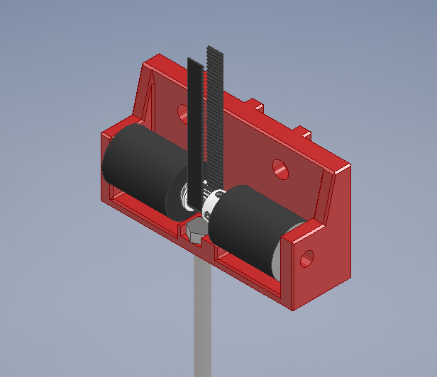
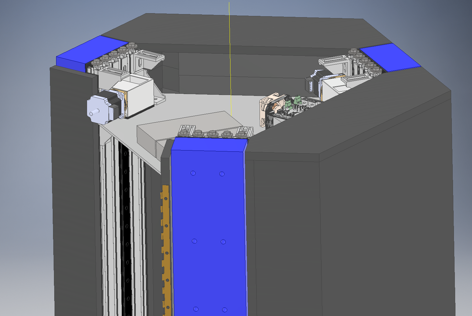
@arhi @theruttmeister The thing is it does not matter whether in what conditions my leadscrews are, because I don't have any. Aha! My machine is a delta, so just belts driving linear rail sliders. Here's a see through view of the motor bracket as I envision it now (and am printing at the moment) and a more overview-y pic of the top of the machine.
I did end up ordering the cheap jaw/spider couplers I linked earlier. I hope the spiders in them are not sloppy, causing a lot of backlash. They should have arrived today, but I have a feeling the shipment will be delay until tomorrow at least.


-
@Nxt-1 said in Battling sources of vibration and noise:
The thing is it does not matter whether in what conditions my leadscrews are, because I don't have any.
in your case the shaft secured between two bearing is what needs to be straight and in that case that "cross/web" coupler works awesome. I never had issues with them having any backlash even on a milling machine. The plastic cross in the middle does ware out on the milling machine and develop some backlash (after many hundreds of hours working) and then you replace it (just the plastic part)
-
So today I received the couplers and they look and feel actually quite decent. I installed them on the brackets from my last post, put the bearings in their new rubber sleeves and installed those as well. I took the new assembly for a spin on the machine and the noise was actually considerably worse believe it or not.
After trying out some different combination of rigid couplers, flex couplers, old brackets and new brackets, my conclusion is that the rubber sleeves around the bearings are a bad idea. I have some long time sensitive prints I need to get done so right now I am running the old bracket with the new flex couplers.
I am not really sure where to go from here. I might look into doing something like the double belt arrangement like @arhi mentioned earlier.