Cantilever bed advice
-
Hi, I was wondering if anyone might have any advice on cantilever bed designs.
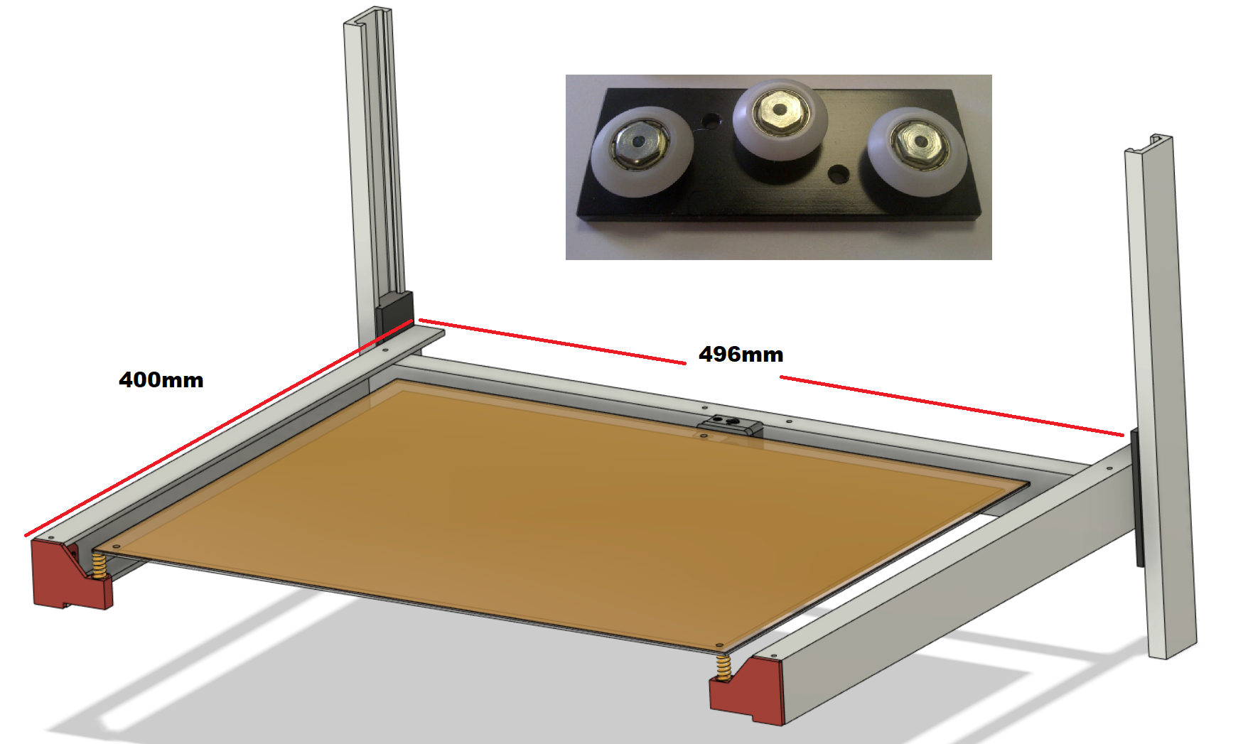
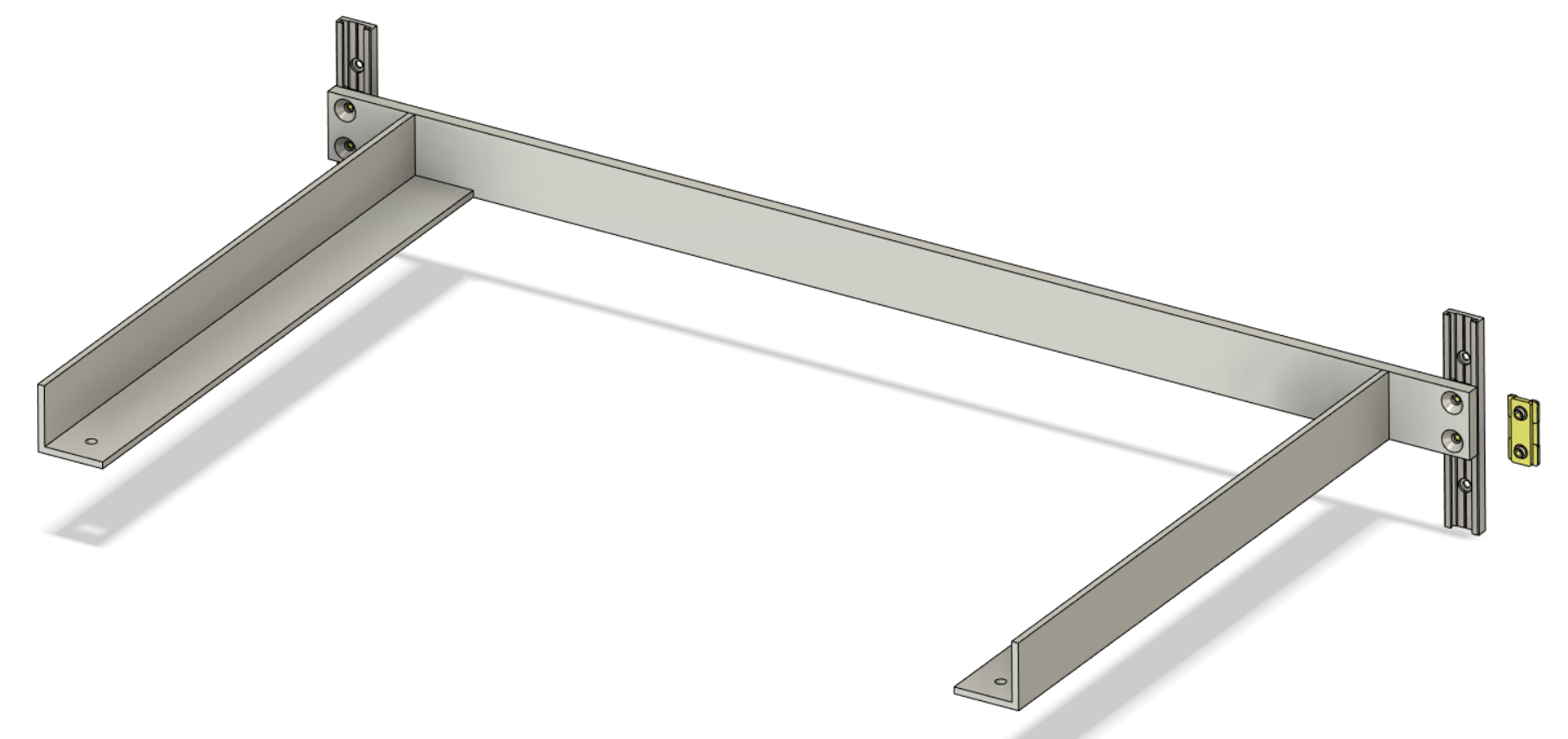
The first image shows my existing bed arrangement (GSF R32 rails) which works fine with the exception of some sagging on the unsupported side. It is driven by a single Z axis motor in the middle between the rails and I want to swap to a simpler setup for the metalwork (As seen in image 2).
The model in image 2 suggests in simulations that it will be significantly stiffer and sag a minimal amount with a 3kg weight, I think it was about 0.2mm at the end. However with the bearing length of only 30mm (Igus N 17) and having tried it with larger bearings (Igus TW-01-20) I'm getting a bit concerned about whether it will run smooth. The Igus T rail guides have a lot of play without a lot of tuning, more than the N guides do, but they also (theoretically) have a much longer area to glide on.
I haven't been able to tune the T guide blocks up enough to remove all the slack (see image 4 - it shows what it looks like without a rail), and when lifting the bed up they work fine albeit a bit stiff, but when I lower the bed by hand there's a lot of chattering. I have a suspicion that if I flip the bearings upside down that the behaviour would be reversed in this case.
Am I ignoring too many cantilever design rules or is the chattering simply down the the slack T rail bearings?


-
Hi,
you're putting a lot of torque on the bearing blocks, which leads to a lot of binding (what you call "chattering"). This might work with stiff ball bearings, which still move under high load, but not with gliding bearings such as igus. The forces in the bearing surface become too high to allow a smooth gliding motion.
To eliminate the torque on the bearing block, either move the linear rail to the center of the bed's side (which would have been the sensible thing to do in the first place), or add another bearing block per rail that is spaced to the original one at least half of the distance between rail and the bed's center of gravity.
igus calls this the "2:1 rule", check out this document: https://www.igus.de/_wpck/pdf/global/2zu1Regel.pdf
HTH, Niklas
-
Cantilevers really only work if the guides are very rigid and the bearings have no play. Even at that, there will be a low frequency resonance that will have the bed bouncing like a diving board simply because of the movement of the XY mechanism. You can avoid that by operating the XY mechanism slowly - i.e. print slowly - but who wants to do that?
I have/had a Cubex Duo printer with a cantilevered bed that printed very nicely as long as print speed was kept <40 mm/sec. Ugh! That probably explains why I haven't done anything with it in a few years.
If you must cantilever, I think it would be better to use two screws, located as closely as possible to the guides. It would be better still to add a third screw to support the free end of the bed- then it won't bounce.
-
Thank you for both your comments, I have very little experience with cantilevers and after all the time I've spent trying to work it out in a cost effective way I thought it best to just ask.
@sonderzug said in Cantilever bed advice:
To eliminate the torque on the bearing block, either move the linear rail to the center of the bed's side (which would have been the sensible thing to do in the first place), or add another bearing block per rail that is spaced to the original one at least half of the distance between rail and the bed's center of gravity.
I thought about that last night, and it seems like what I will have to do. It complicates other parts of the frame so I had been reluctant to try it as I had been trying to keep costs down. To test it from the sides, I should be able to modify the side panels, though it will take some fresh aluminium to span the gap. My contact at a certain company had not commented that the cantilever design would not work when I shared it.
@mrehorstdmd said in Cantilever bed advice:
Cantilevers really only work if the guides are very rigid and the bearings have no play. Even at that, there will be a low frequency resonance that will have the bed bouncing like a diving board simply because of the movement of the XY mechanism. You can avoid that by operating the XY mechanism slowly - i.e. print slowly - but who wants to do that?
I have/had a Cubex Duo printer with a cantilevered bed that printed very nicely as long as print speed was kept <40 mm/sec. Ugh! That probably explains why I haven't done anything with it in a few years.
If you must cantilever, I think it would be better to use two screws, located as closely as possible to the guides. It would be better still to add a third screw to support the free end of the bed- then it won't bounce.
Printing slowly is really something I don't want to do. The gantry is capable of printing at 200mm/s. Cantilevering seemed like a sensible choice with strong enough supports as I wanted to keep to a single leadscrew. I don't really want to go to two leadscrews as when I had a Prusa clone years ago it was a huge pain, though that was in part to how poor quality it was. I'll post the results of moving it to the sides when I've found the time.
-
@Spargo Moving the extruder carriage at 200 mm/sec is pretty easy. Getting the extruder and hot end to keep up with that motion is the problem.
-
There are good reasons to cantilever the bed (mostly reducing motor count and simplifying alignment in general).
But to echo what others have said, you need to greatly increase the spacing between bearings in Z. So your Igus version needs at least 200mm between bearings. The design you suggested wouldn't move, it would be locked solid. Roller bearings can tolerate higher loading, but even they have limits.
You will in general have to make a cantilevered bed stiffer and stronger, so it will be heavier, plus it will take up a bunch more space in Z (unless you get clever with packaging). But that can be worth it. More rails means more motors and more risk of over-constraint (which makes stuff bind up).
For any Z stage, cantilevered or otherwise, longer bearing lengths in Z will always help. But in a cantilever the longer the better.
And just moving the same short bearings to the center of the sides might stop them binding, but those igus N bearings are not designed to be stiff (only cheap)... so you will probably have quite a bit of vibration and slop in the bed.
Even with the T bearings, I'd suggest adding an extra carriage to each rail. -
Yeah I'm going to move the bearings to the middle and have some spaced. Looking at having a new design for that at either the end of this week or next depending on it I can fit it in or not.
@mrehorstdmd I've had it actually laying plastic fine with the head moving at those speeds, 0.2mm layers. It's using a volcano with a 0.8mm nozzle and a 48mm high torque stepper motor on the extruder. Moving XY is fine up to 350mm/s.