Black Beauty Arises!
-
@Nemesis1782 In my case, I wanted the tool carriage gantry to be flat/horizontal rather than vertical. It was just an easier design for me.
Stacking pulleys or offset belts still seems more complicated to me. Harder to design/assemble. For instance, if you stack pulleys, you have to support the shaft at both ends the force from the top belt will tend to bend the assembly over. Just my opinions though.
-
@gtj0 thank you for taking your time and answering in detail!
The 40 drylinN series are an experiment for my Delta. I stupidly cheaped out on it with Machifit MGN12 clones and 2 of the 3 were disastrous. Even after careful cleaning and lubing they remain stuck. The one carriage that actually isn't stuck has play in it. Lesson learned.
Not sure what way I'd go on a coreXY with Igus, really mostly depending on the performance of the 40 series. Supported drylin W do seem like a nice option, especially as they have adjustable preload carriages available. But I also don't want to rule out drylin N 20-ish with a proper floating/fixed arrangement as I'd prefer a non-cantilevered mount for the hotend. Especially since I want to mount a Hemera on it. I have the advantage that Igus is readily available for private persons in my country with quick delivery. Genuine Hiwin are either super expensive or I'd have to wait 1 month from China or even longer from the US for usable robodigg clones..
I'm a tinkerer, so I need stuff available on hand that I can play with.. apart from the noise factor the most important decision for Igus..
-
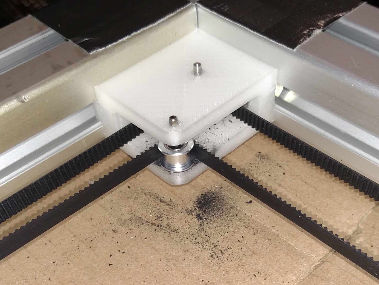
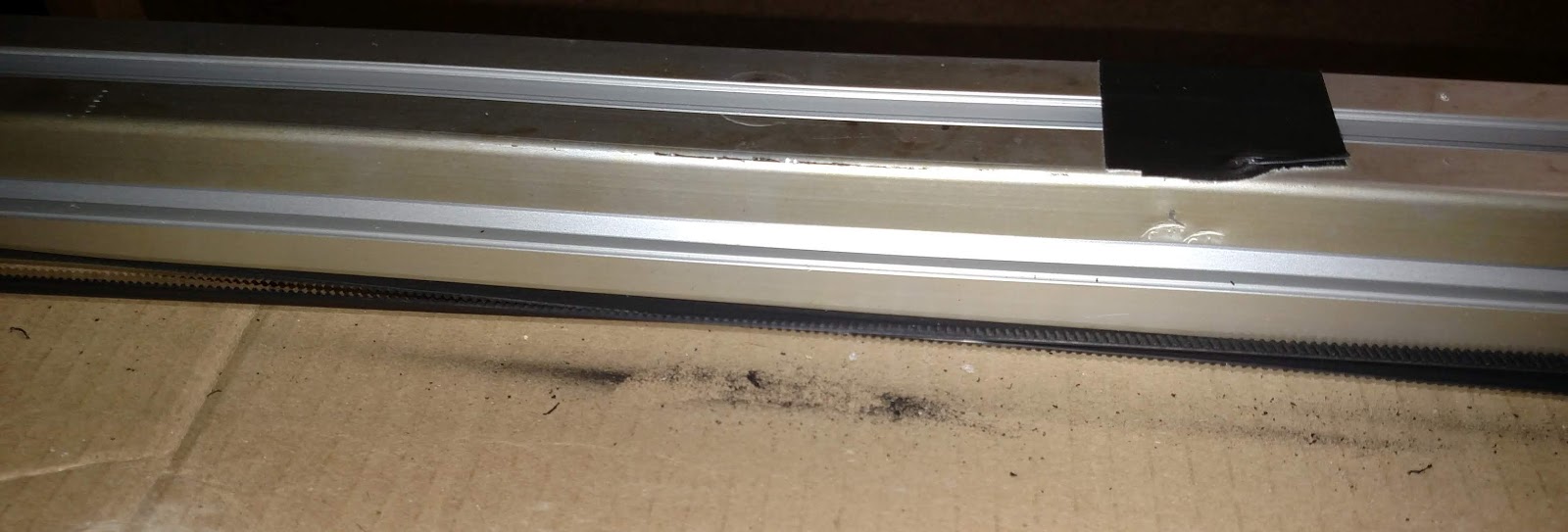
If you put the belts on two levels, you can stack the pulleys so in theory, at least, use less space for the mechanism. The location of pulleys is critical to ensure that the belts run parallel to the guide rails, so by stacking the pulleys there are fewer places to have to worry about exact placement and fewer chances to do it wrong. Stacking the belts means you don't have to twist them and take extra measures to ensure minimal wear at the crossover point. I have found twisted belts tend to ride on the pulley flanges more than untwisted belts and that can result in wear on the belts. Belt teeth contacting smooth pulleys can make a zipping noise, but you have to be running the mechanism unrealistically fast for it to be noticeable.

That was in the sand table that is 1.7m x 0.75m between pulleys. Part of flange-riding may have been due to the weight of the belt making it sag, and part was probably due to the forces produced by the twist in the belts.
Similar wear at the belt crossing, back side against back side:

I recommend supporting pulley axles at both ends whether you stack the belts or not. It's easy to do with printed parts as shown in the above photos and not difficult if you use rectangular aluminum tubing (you can cut it with a hacksaw if you have to). It helps to have a drill press to drill the holes, or even better, a milling machine.

The aluminum tubes could easily be replaced by bulkier printed parts if you have absolutely no access to tools to cut and drill aluminum.

-
@gtj0 I'm also working on my own CoreXY design. The reason I did not choose to do the twisty thing is because I'm afraid of damaging the belts.
-
@Nemesis1782 It's definitely a valid concern. You can only do it if the span is long enough to allow a more gradual twist. The genuine Gates belts also help because they have Nylon face and
fiberglass cords. I also don't have the machining tools or skills to produce the required brackets.
-
@gtj0 I think it would be little trouble to design 3D printable brackets to replace the aluminum tubes. Just print with thicker walls and filleted inside corners to maximize rigidity.
-
@mrehorstdmd said in Black Beauty Arises!:
@gtj0 I think it would be little trouble to design 3D printable brackets to replace the aluminum tubes. Just print with thicker walls and filleted inside corners to maximize rigidity.
Sure! I didn't mean to imply that one approach was better than the other. I just meant that the approach I took was simpler for my situation and my liking.
-
Some questions on the Igus rails, for you. I've been following this for quite awhile (since the Hypercube Overkill thread on RepRap.org), but now I'm getting close to ripping off the motion platform. This has been quite the project, and become very impressive.
You mention using 17mm, and overmolded. The only 17mm option on their site is the solid plastic carriages only, and that looks like what I see if the few photos where they are clearly visible, which was on the previous printer. The other options are there for 27mm and 40mm, though.

While the original design more or less explains the rail and toolhead layout on your newer revision, based on your experience with these rails, would you foresee any problems with them used in more common cantilevered toolhead layout (provided the use of 2 X rails, spaced at least as far apart as the printhead's center of gravity is from the front rail)?
Did you opt for a fixed/floating mix on the X axis, or all 4 fixed?
-
@yellowedplastic said in Black Beauty Arises!:
Some questions on the Igus rails, for you. I've been following this for quite awhile (since the Hypercube Overkill thread on RepRap.org), but now I'm getting close to ripping off the motion platform. This has been quite the project, and become very impressive.
Thanks!
You mention using 17mm, and overmolded. The only 17mm option on their site is the solid plastic carriages only, and that looks like what I see if the few photos where they are clearly visible, which was on the previous printer. The other options are there for 27mm and 40mm, though.

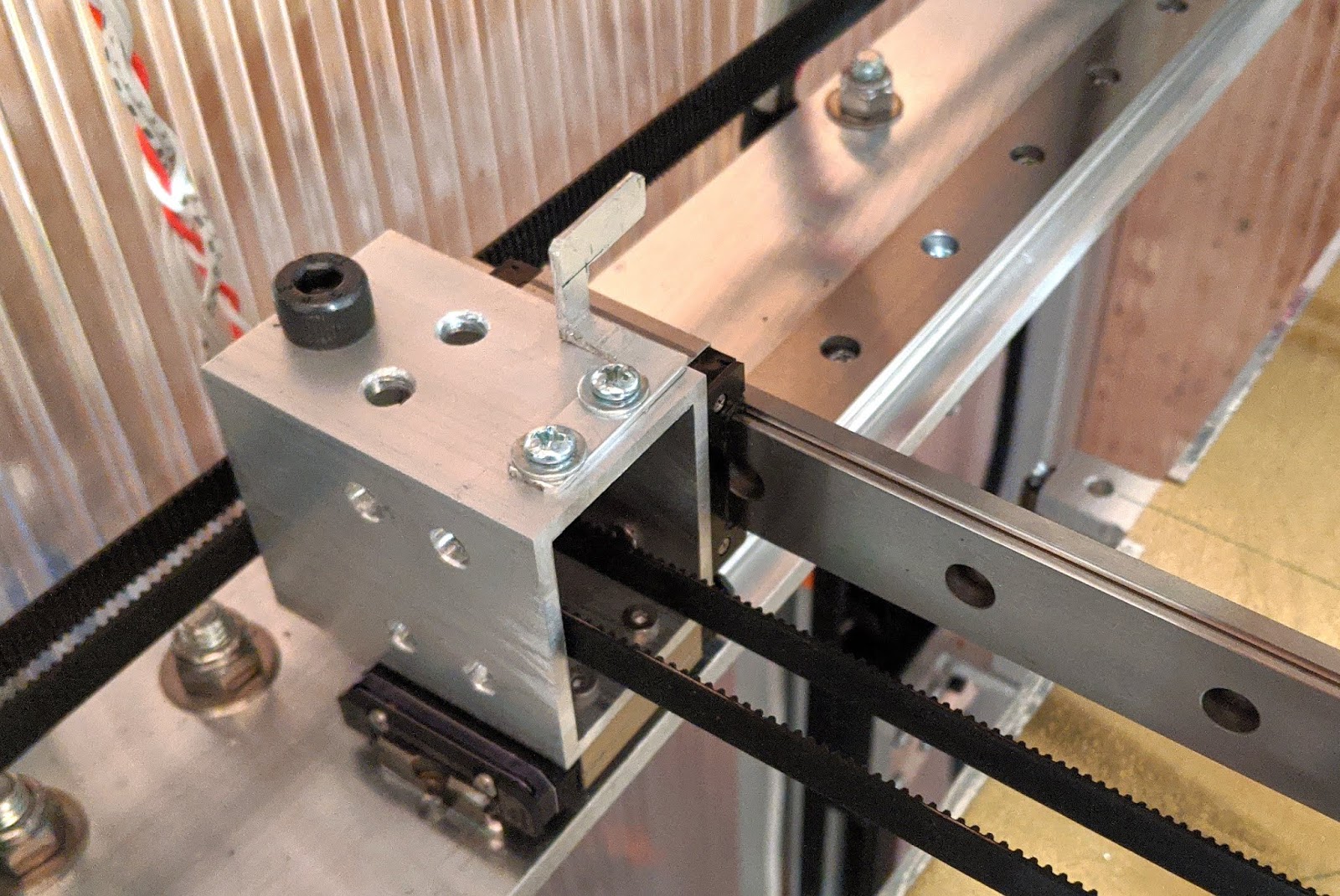
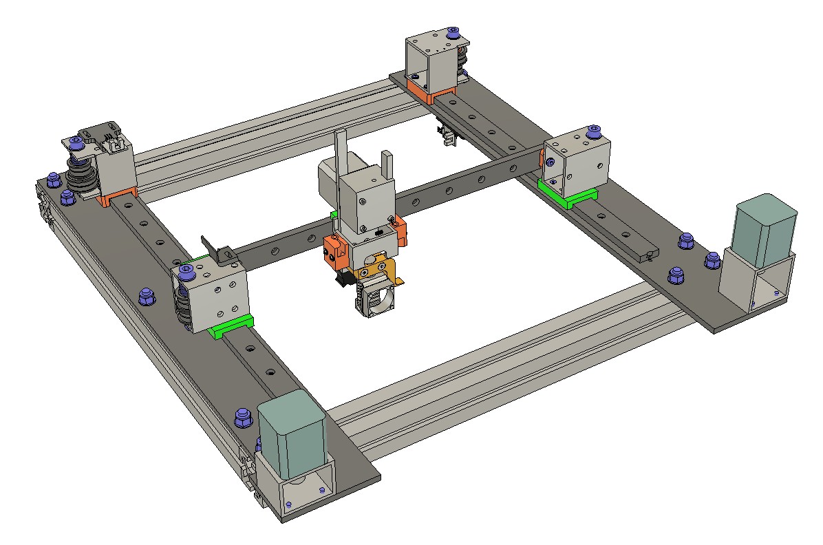
Yep they are all 17mm and solid plastic. The 4 on the tool carriage and the 2 on each of the Y rails are the 40mm long non-floating versions. The slider in each of the Z rails are 30mm long non-floating. The 27 and 40mm wide versions were just too big for me.
While the original design more or less explains the rail and toolhead layout on your newer revision, based on your experience with these rails, would you foresee any problems with them used in more common cantilevered toolhead layout (provided the use of 2 X rails, spaced at least as far apart as the printhead's center of gravity is from the front rail)?
I'm trying to picture your arrangement. With a cantilevered toolhead, I'd expect the rails to be "vertical", one above the other with their open faces facing the front of the printer, yeah? Or am I thinking something different? A lot depends on the length of the unsupported span and the mass of the toolhead but the rails are stiffest in that orientation so I wouldn't expect a problem. You may want to think about using a single 40mm wide rail and carriage though.
Did you opt for a fixed/floating mix on the X axis, or all 4 fixed?
In my design all 4 are fixed but that's because I have the ability to adjust the center-to-center distance of the rails. I align the front X rail so it's square with the Y rails, then adjust the back X rail so the toolhead slides with consistent friction across the span and with no twisting.
-
@gtj0 said in Black Beauty Arises!:
I'm trying to picture your arrangement. With a cantilevered toolhead, I'd expect the rails to be "vertical", one above the other with their open faces facing the front of the printer, yeah? Or am I thinking something different? A lot depends on the length of the unsupported span and the mass of the toolhead but the rails are stiffest in that orientation so I wouldn't expect a problem. You may want to think about using a single 40mm wide rail and carriage though.
That's still up in the air a bit. I'm planning to implement a Frank Herrmann style tool changer, though any tool changer will be easier with a cantilevered head. I doubt I'll be putting more than 500g on it, but am aiming for much less. The whole machining thing is new to me, so I'll probably be spending some evenings learning and wasting aluminum at my makerspace, figuring out what's most practical to end up with. Two horizontal rails of 17mm, or one of 27mm or 40mm, should allow for the least weight with a lot of rigidity, and least alignment work (IE, make the whole axis out of one piece of aluminum, like E3D's/Jubilee's, with rail lips and screw holes, with most of the work done by CNC milling), so I would lean that way, for now.
Did you opt for a fixed/floating mix on the X axis, or all 4 fixed?
In my design all 4 are fixed but that's because I have the ability to adjust the center-to-center distance of the rails. I align the front X rail so it's square with the Y rails, then adjust the back X rail so the toolhead slides with consistent friction across the span and with no twisting.

-
@yellowedplastic said in Black Beauty Arises!:
@gtj0 said in Black Beauty Arises!:
I'm trying to picture your arrangement. With a cantilevered toolhead, I'd expect the rails to be "vertical", one above the other with their open faces facing the front of the printer, yeah? Or am I thinking something different? A lot depends on the length of the unsupported span and the mass of the toolhead but the rails are stiffest in that orientation so I wouldn't expect a problem. You may want to think about using a single 40mm wide rail and carriage though.
That's still up in the air a bit. I'm planning to implement a Frank Herrmann style tool changer, though any tool changer will be easier with a cantilevered head. I doubt I'll be putting more than 500g on it, but am aiming for much less. The whole machining thing is new to me, so I'll probably be spending some evenings learning and wasting aluminum at my makerspace, figuring out what's most practical to end up with. Two horizontal rails of 17mm, or one of 27mm or 40mm, should allow for the least weight with a lot of rigidity, and least alignment work (IE, make the whole axis out of one piece of aluminum, like E3D's/Jubilee's, with rail lips and screw holes, with most of the work done by CNC milling), so I would lean that way, for now.
Did you opt for a fixed/floating mix on the X axis, or all 4 fixed?
In my design all 4 are fixed but that's because I have the ability to adjust the center-to-center distance of the rails. I align the front X rail so it's square with the Y rails, then adjust the back X rail so the toolhead slides with consistent friction across the span and with no twisting.

Gotcha. So in that arrangement, you could go with either 2 smaller rails or one 40mm one. The 40mm rail makes alignment easy but it's heavier and you can't see through it. If you go with 2 rails, you'd use 2 carriages in the top rail and just 1 in the bottom rail. The bottom one could swivel to prevent binding.
-
@mrehorstdmd Interesting wear on the idler. Figures me a bit; would you agree that probably the debris there is cause by the belt rubbing over each other, with debris falling right down at the spot and another part at the idlers where the belts "Bend open"? Or do you think the wear is caused by the belt rubbing on the idlers itself?
@gtj0: did you notice any debris on your printer yet? You have the spacer in the middle that prevents the rubbing between the belts, so...
Also what is the minimum length you feel needed for the "twisting trick"?
I also do hard to figure out reading post if it is really better to have smooth idlers v.s toothed ones. Pffff. Feels to me that toothed idlers are not an issue because there is no load on them...
-
@QuintBrand It's hard to say. I suspect the belts rubbing on the flanges of the pulleys were causing some wear in addition to the belt to belt contact. Gates belts have nylon facing on the teeth, not the back side of the belt, so the belt on belt wear would still occur. In some machines that cross the belts on one level people add a plastic separator, usually PTFE, to keep the belts from sliding against each other.
-
@mrehorstdmd Ok, so your feeling is that wear was at three places: left and right Idlers and in the middle the belt contact. THX.
-
@QuintBrand said in Black Beauty Arises!:
@mrehorstdmd Interesting wear on the idler. Figures me a bit; would you agree that probably the debris there is cause by the belt rubbing over each other, with debris falling right down at the spot and another part at the idlers where the belts "Bend open"? Or do you think the wear is caused by the belt rubbing on the idlers itself?
@gtj0: did you notice any debris on your printer yet? You have the spacer in the middle that prevents the rubbing between the belts, so...
Also what is the minimum length you feel needed for the "twisting trick"?
I also do hard to figure out reading post if it is really better to have smooth idlers v.s toothed ones. Pffff. Feels to me that toothed idlers are not an issue because there is no load on them...
Oops, lost track here. Been too busy with other stuff.
Nope, no debris at either the center or the idlers and the printer's been very busy. I have a belt span of about 650mm and wouldn't attempt the twist with a span of less than maybe 550mm. I have no data to back that up though as I haven't tried any shorter spans. As for toothed vs smooth idlers... It's true that there's no drive load of course but the inward force of just the belt teeth on a smooth idler surface would seem to cause the teeth to compress and expand more than if the teeth were riding in mating grooves of a toothed idler. Whether this is an issue in real use I'm not sure. I went with the toothed ones because it just made sense to me.
-
@gtj0 thanks for the answers! Great, I'll go twisted in my core to be too. So thanks for sharing, you helped me a lot!
Thinking about the idlers... Yes toothed could be better actually that way
 . I go toothed too, but saw some discussions bearings would be better. Nah, I like the toothed stuff!
Cheers!
-
@QuintBrand said in Black Beauty Arises!:
@gtj0 thanks for the answers! Great, I'll go twisted in my core to be too. So thanks for sharing, you helped me a lot!
Thinking about the idlers... Yes toothed could be better actually that way
 . I go toothed too, but saw some discussions bearings would be better. Nah, I like the toothed stuff!
Cheers!
Ah toothed idlers as opposed to bearings not smooth idlers. The bearing sandwich, such as that used by @mrehorstdmd, has a large enough diameter that there's much more surface area to spread the load so having the belt teeth ride over that smooth surface is not an issue. I went with the idlers just because of space constraints.
-
@QuintBrand The problem with the toothed pulleys is that the bearings in them are very tiny and wear out quickly. They typically have 3 or 5 mm bore which means the balls have to be very small which puts a lot of force on the races.
The 3D printer pulleys, smooth, but with 3 mm bore, I originally used in my sand table lasted for about a year of sporadic use before they started squeaking and binding.
A Gates manual about timing belts recommended a minimum of 9 teeth in contact with the pulley surface if using smooth pulleys. The belts bend over about 90 degrees of each pulley in a corexy machine. So if you're going to have 9 teeth over 90 degrees, that suggests 36 teeth going around the pulley. With 2 mm pitch, the circumference should be approximately 72 mm (a little less, actually), which leads to about 23 mm diameter. 608 bearings are 22 mm in diameter, are made in huge quantities for skates, motors, and machines, so are very cheap and readily available. They will last long time under the loads presented by a 3D printer.
-
Thanks for the nice additions a remarks! Wear and tear is not something I was think of to be honest ;-). I've also studied some of the Gates documentation, which is really nice till you want to do the math yourself: have you ever found the Specific Stiffness of GT2? I didn't unfortunately and once you start searching for the specifics I got lost in the fast amount of info ;-).
I thought driven pulleys require a lot of teeth, but was not away non-driven should be too. Makes sense when it comes to compression of the belt on the idlers though.
Most pulleys are 21 tooth on Ali, bit strange in view of your comments. These bearings are tiny indeed ;-0!!!
-
Someone asked for a link to the pics...
https://imgur.com/gallery/H9qKVcL