Collaborative pellet extruder test plant
-
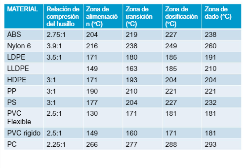
Hello everyone, I built a pellet extruder and I plan to put it to the test, so it will be available to users to run the tests that occur to them, I hope they help me find the best solution to the problems found in the Road, initially I am testing Polypropylene, the design consists of a nema 23 engine of 2.5Nm of torque, 4.2A, use 48v Dc to power the dq452ma driver, 200 steps / rev and has a 15: 1 speed reducer, use a 460mm full length wood auger and 331mm effective length, I use 4 independent heating zones listed ascending starting at the nozzle, and there is a fifth temperature sensor in the hopper part to monitor the temperature in that area and control the cooling fans, the heaters operate at 110v AC and I use SSR to control them, to calculate the steps per millimeter I have measured the pitch of the auger thread as shown in the attached image of the screw or that measurement gives me a total of 27.3mm so with that data and using x16 micropasses, the steps / mm found are 1758 steps / mm, I have 1.8mm and 2.8mm nozzles, the temperatures are being controlled at the values shown in table 1 for polypropylene (PP).


Definitions:
cylinder or sleeve: it is the perforated bar through which the screw or drill passes and it is the one who transfers the heat to the plastic granulesscrew : it is who moves the plastic granules towards the nozzle
So far I have tried to move the extruder from DWC manually, the temperature is stable and it takes about 10 minutes to reach the temperature with the entire cylinder filled with hard and cold material (polypropylene), the temperature in the part of the hopper, which should be kept as cold as possible, remains at 40 degrees Celsius, the hopper is designed to avoid jams, I'm still looking for an insulating material to wrap the cylinder and prevent some heat from dissipating in the air.
What worries me now in a preliminary way is that from DWC the highest speed I can send to the engine without losing steps is 10mm / s which seems to be a problem for me, at that speed the amount of material that comes out of the 1.8mm nozzle is very large, but if I'm going to slice an object to send it to print I can't use print speeds greater than 600mm / min because they would cause the extruder to not move due to lack of torque, and according to simplify3d the time of Impression goes from 3 hours using 50mm / s to 6 hours which makes no sense to me.
as I said is my preliminary observation, so any appreciation or advice in this regard is welcome, I plan to mount an extruder in the printer but I'm a little short of time, by the University, and that will take me some time because I need redesign some parts so that it can support the extruder, I also plan to design a system to vacuum pellet pellets directly from the bulk located to the extruder hopper located about 2 meters high and use some sensor to detect the lack of pellet.
some prices in dollars on the raw material
The bulk of transparent polypropylene pellet of transparent color today is 25 kg for 44 dollarsThe pigment bag to give color to the molten pellet costs 4 dollars, weighs 1kg and yields enough to give color to 25kg of pellet
Attached some photos, if you want to see beyond you can request CAD models or I can disassemble the extruder to a certain part.
know that there are better motors that can give me more torque and speed, like an AC or DC servomotor, but in this case it is what I had at hand, and I would like to see how feasible this system before making major investments!


-
Very nice! i think you could save weight by making the hopper out of something lighter than steel, maybe lasercut and bent acrylic.
Could you show some pictures from inside the hopper?
How did you realize the 90° force transmission from the stepper to the screw? -
I would be interested in trying this out. Let me know how I can help.
-
Very cool, definitely interested in following your work!
-
Hello everyone, here I present two more photos, I made the steel hopper because it was what I had at home, but thanks to the modular system, I can later change to aluminum, it must be made of metal so that it can dissipate the heat and withstand the forces exerted by the motor to the screw pushing material.
Now I need to know what can be the best configuration for the engine such as accelerations, speeds, speed changes and micropasses, and what could be the way to test an impression, considering that the slicers work with millimeters of filament without melting.
I would like to know about your ideas and thoughts about it, right now there are very few tests I can do, but I plan to have several tests ready to try in a few days.


-
I know that the main concern of this type of systems, are the retractions, but from what I have been able to find out, the polymers have certain characteristics, it may be the same polymer but for different types of technologies their characteristics change, for example when they melt they flow as a liquid, but rather as a hot dough, and in theory that prevents material from dripping down the nozzle, but in case these drips occur, I plan to build a pneumatic system that stops and opens the nozzle very fast for extruder displacements .
Here you can find a system that closes and opens the nozzle.
https://wiki.utopiamaker.com/index.php/Extrusor_de_Pellets_para_Impresión_3D