Thank you for the answer.
It was enough to change the M574 Y1.
Posts made by Cossack
-
RE: The printer is trying to move outside of the work areaposted in Duet Hardware and wiring
-
The printer is trying to move outside of the work areaposted in Duet Hardware and wiring
Hello,
I have a Cartesian kinematics printer with X-axis endstop at the minimum end and Y-axis endstop at the maximum end.
Electronics is a duet 2 wifi. In config, I have set:M574 X1 S1 P"xstop" ; configure switch-type (e.g. microswitch) endstop for low end on X via pin xstop M574 Y2 S1 P"ystop" ; configure switch-type (e.g. microswitch) endstop for low end on Y via pin ystop M574 Z1 S1 P"zstop" ; configure switch-type (e.g. microswitch) endstop for low end on Z via pin zstop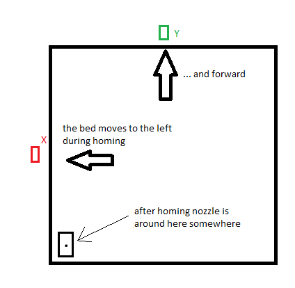
When I manually control the movement of individual axes, everything works as it should. X + 10 moves the carriage to the right and Y + 10 moves the bed towards me.During homing, the carriage and the bed normally approach the limit switches and it seems to me that they are working properly. The Y axis limit switch works rather because when I press the limit switch and check the status of M119, it shows:

As I understand it, after homing, the beginning of XY is in the lower left corner of the bed. However, when it generates a program in Cura and I run it on the printer, it wants to go forward beyond the Y axis up after homing. I do not understand why. I include the initial part of the code.
;FLAVOR:RepRap
;TIME:12744
;Filament used: 12.4797m
;Layer height: 0.2
;MINX:62.2
;MINY:62.2
;MINZ:0.3
;MAXX:177.8
;MAXY:177.8
;MAXZ:100.1
;Generated with Cura_SteamEngine 5.0.0
T0
M190 S60
M104 S200
M109 S200
M82 ;absolute extrusion mode
G28 ;Home
G1 Z15.0 F6000 ;Move the platform down 15mm
;Prime the extruder
G92 E0
G1 F200 E3
G92 E0
M83 ;relative extrusion mode
G1 F1500 E-6.5
;LAYER_COUNT:500
;LAYER:0
M107
G0 F3600 X69.942 Y70.755 Z0.3
G0 X63.804 Y80.699
;TYPE:SKIRT
G1 F1500 E6.5
G1 F900 X63.963 Y80.264 E0.02311
G1 X64.395 Y79.181 E0.05817
G1 X64.569 Y78.778 E0.0219
G1 X65.059 Y77.726 E0.0579
G1 X65.266 Y77.315 E0.02296
I'm not sure, but I guess it happens in this line.
G0 F3600 X69.942 Y70.755 Z0.3I also tried to change the axis limit to be smaller or larger than the bed size, but the same thing still happens.
; Axis Limits
M208 X0 Y0 Z0 S1                               ; set axis minima
M208 X240 Y240 Z230 S0                         ; set axis maxima
What am I doing wrong ?
-
Connecting the limit switchesposted in Duet Hardware and wiring
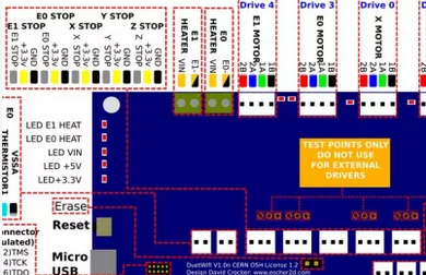
I want to connect my limit switches to duet 2 wifi. I have limit switches like below.
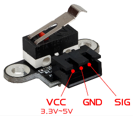
So far, I have not tested anything and connected so that the VCC cable is connected to the middle endstop pin on the board, GND to the right, and SIG to the left, according to the diagram.
In the limit switch options, I have a lot of different options from which I don't know which to choose.
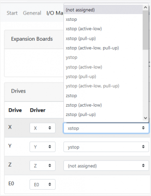
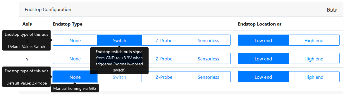
Could someone explain whether the switches are well connected and what configuration options will be appropriate?
Thanks in advance for all replies and sorry for my English.