Redesigned the MFM housing
-
Would shielded usb cable work? I believe I'm close to solving the problem with my sensor.
The holes in the housing that hold the bearings were too large. I reprinted the housing with different settings and filament until I had to seat the bearings with a bit of force. I then ran a 9 hour print and only had three stops. One of those stops I observed the extruder motor skipping steps. I don't know why it did it but I increased the hotend temp and adjusted the extruder tension and it completed the print.
I did have one other problem. The agc value was erratic with the new housing going from 71 to 94. I found the rotating assembly was now able to move in the axial direction. I sanded the inside faces of the housing to get the parts a little closer. My current agc is stable at 81 with no false positives over 2 more hours of print time. I still have one problematic print I want to test so fingers crossed, I now understand why they recommend this housing to be printed on an sls printer. -
@idodgeads I'm still waiting for some shielded cable to arrive to test, but I do believe there to be an issue with interference in my setup, at least. It's not what you'd call ideal. Genuine skipping or under extrusion gives what I'd call "sane" values: 40% to 103%, for example. What I believe to be interference gave readings more along the lines of -30% to 200%... Not really believable and not a mechanical issue I could find at all. USB cable actually might be a good call!
Regarding mag and AGC: One of my test criteria is how stable they end up being. There's always a little bit of "settling" on a freshly printed housing as the plastic stress relieves slightly and adjusts to whatever stresses are imposed on it with the fasteners, but it's not much. Typically mag may vary by maybe 2 or 3 either way then settle. Disassembling and reassembling usually prompts a change by that much too. I've aimed for (and achieved) light press fits on the critical features, at least on the printers I have.
Do you want to try the current version I'm testing? It would be valuable feedback if you're happy to do so!
-
@idodgeads said in Redesigned the MFM housing:
Would shielded usb cable work
Yes
 It's actually perfect for the job!
Thanks for that, sometimes you forget what's right under your feet! I'm got to crimp up a shielded cable and go print some circles....
-
 undefined Lo-Fi referenced this topic
-
@lo-fi
No problem, I would be glad to test your design. My printer is slow but its pretty accurate if I get the slicer set right.
As I'm not an electronics wizard, I'm wondering about grounding the shielding in the usb cable. Does it need grounding at one end, both ends? Maybe a ferrite choke would also help here. I wish I had an oscilloscope still, I'm sure that would show any noise on the data wire of the mfm. I'm thinking of making up a shielded cable for my bltouch. I just replaced my v1.0 with a new v3.1 and I still have random high spots in the height map but most of the wonky behavior the old one had is gone. -
Housings for the V1 rotating assembly:
MFM Housing - Lo-Fi Lid - mag V1.stl
MFM Housing - Lo-Fi Base - mag V1.stl
MFM Idler - Idler Mount V1.stlI've tested these printed from both my printers with different filaments. All successful right off the print bed with no sanding or shimming and very little variation in Mag or AGC.
The only super critical print setting is to use 0.1mm layer height. I really cannot stress this enough. Moving down to 0.05mm is fine, as is any other layer height the divides neatly into 0.1. Anything else is likely to land you with some "odd" dimensions that are really quite important. Otherwise, just do what you'd normally do for accurate functional prints. In Cura, the "Horizontal Expansion" setting can be quite handy to compensate for any deviation of your printer - I'm sure other slicers have similar settings.
I've designed for 0.4mm line width, so best to stick to that. 10-20% infill of any type that ties the walls to the top/bottom will work fine. I used lines an gyroid while testing. You should get 3 x whole lines in the 1.2mm "walls" of the lid.
The lid might need a light deburr if you get some elephants foot on the first layer.
I opted for using flanged RC servo screws to mount the board, though you can easily drill and tap to
M2.5 for the board mounts. All the supplied hardware is used as standard otherwise.Push the PTFE tube into the housings so it's close to, but not interfering with the hobbed section. This runs in further than the official housing and is best done before the rotating mag assembly is installed so you can be sure where it ends up. Running the point of a knife or deburring tool inside the entry to the outgoing PTFE completely eliminates any snag when loading filament.
The bottom bearing is best pressed in with the head of an M5 cap head screw if this is required. This puts the force purely on the outer race, though not much should be needed all other things being equal. As explained in the original post the seats have a slight taper which seems to account nicely for variations in prints and gives a snug fit without any fussing. The bearings snap nicely into place on all my prints now with no play or fettling needed.
The idler carrier halves will need gluing together around the bearing as per the original and need no special attention. I'd advise a tiny blob of glue where the stubs meet inside the bearing, but careful with the bearing itself, obviously.
I'll move on and test V2 now
 In the meantime, please do treat this as a development prototype and of course send some feedback if you try it! I had a stupid moment this afternoon where I forgot to add the idler bearing altogether and was annoyed I got one or two under extrusion warnings. That was until I figured out what I'd done!
 -
 undefined Phaedrux pinned this topic
-
@lo-fi, I just wanted to say thanks for this design! I have two different MFM's (a 1.7 and a 1.7b), using this mount has actually made the 1.7b useful and reliable. Before switching to this mount, I honestly just kept the MFM disabled and used a microswitch in front of the MFM for filament monitoring. I always wanted to get the sensors working reliably, though I never could get consistent performance out of them. The other day I decided to try troubleshooting them again and came across your post here. Wow, what a difference. Thank you again so much for actually making my sensor useful.
I hope that this model will be added to the doc page for the MFM when you and Phaedrux think it's ready. I think there are probably other people who will appreciate it too.
-
@grudairian Wow, that's great news! I'm so pleased it's been helpful

How did you find the build process? Did you have to sand or file anything? If you wouldn't mind posting your mag and agc readings after a print I'd be most grateful too.
-
I'm happy with the V2 assembly, so I've uploaded everything to a GitHub repo:
https://github.com/KerbalFoundries/Duet-Magnetic-Filament-Monitor-Housings
You'll find both V1 and V2.
Happy printing

-
@lo-fi Here's my print of your redesign. I'm really happy with it. I followed your settings and it printed great. A little sanding and trimming was required to get the halves to fit but they fit well. I used pla on the housing and pla+ for the idler. Once I redo the
print head and x axis on my printer, this is going on there over the top of an lgx lite on a custom mount. Thank you for putting forth the effort and making your design public
-
@idodgeads Fantastic, thanks for the feedback!
-
 undefined jay_s_uk referenced this topic
-
@lo-fi Hey man, I just wanted to thank you, new housing is working great!
-
@brotherchris cheers! Nice to know it's working out

-
 undefined infiniteloop referenced this topic
-
Thank you for the design , the original i printed skipped.
I noticed without connecting it to the duet.
It will probably work when printed with very tight parameters or with a resin printer.
Your design works good for me, have printed a few objects and it works fine.
Tested the runout function and it is really great! Thanks!

-
@thooijer-0 said in Redesigned the MFM housing:
Thank you for the design , the original i printed skipped.
I noticed without connecting it to the duet.
It will probably work when printed with very tight parameters or with a resin printer.
Your design works good for me, have printed a few objects and it works fine.
Tested the runout function and it is really great! Thanks!

Thanks! I'm really glad it's working out.
-
 undefined infiniteloop referenced this topic
-
 undefined invertmast referenced this topic
-
@Lo-Fi said in Redesigned the MFM housing:
UPDATE 14-04-22: Now released here: https://github.com/KerbalFoundries/Duet-Magnetic-Filament-Monitor-Housings
Hello!
I'm fairly new to actively posting here, but been using Duet/RepRap Firmware for a while now and recently got tempted to buy a filament monitor after having one or two issues with long prints getting ruined. And because it's a cool little gadget. Who can resist a cool gadget, right?
To cut a long story short, I had a few issues. Some of those (sensorError) were due to loose crimps and something that got tweaked in one of the 3.4 release candidates that dc42 was kind enough to clue me in on. The other issues was "tooLittleMovement". After a while I figured out that I had a few issues with the printed case. In fairness, I know it's supposed to be resin printed really, but I don't have a resin printer. I do have some 3D CAD skills and a love of tinkering, so I set about first recreating the existing design, then tweaking it. Editing STL files is not my idea of fun, so I redrew it in OnShape.
I came up with a few design goals and tweaks:
-
Keep the filament path clear of anything but the PTFE inserts, hob and idler.
-
Align the PTFE so the filament is lightly pressed against the hob even before the idler comes into play
-
Add slightly more clearance for the hob and idler in the filament region
-
Add an indent to keep the idler spring in the correct position
-
Achieve a tight fit for the plastic collets holding the PTFE
The housing I came up with worked a treat, I'm happy to say.
Pic for comparison:
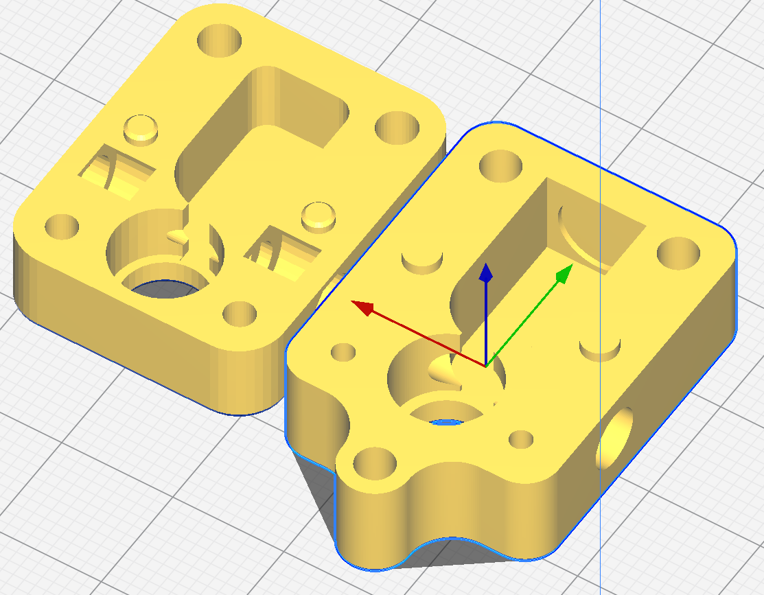
I felt an extra mounting lug couldn't hurt either.
Fast forward a little bit... I ended up spending some time on the forum and chimed in on a few threads where people had similar problems and shared my design a few times. It's a funny thing, though: Once I start sharing out stuff I create, it's hard not to want it to be a good as it can be.... I've been down this rabbit hole before making a KSP mod a few years back, but let's not get sidetracked! It's an enjoyable thing getting involved in an open source project/community, so why not?
I printed and tested many prototypes:

Given that this needs to be printable on any printer, the sane thing to do is print it on the worst machine possible. In my case, it's an ANET A8. I can hear what you're thinking... "You came in that thing?!? You're braver than I thought!" In my defence, it was my first printer, has been modified and runs RRF (though on a Fly CDY V3 - I hope I'll be forgiven, I couldn't justify a Duet for this one). However, it's got a horrid build bed and no bed compensation. Realistically a worst-case scenario for most people playing with Duet, I suspect.
Anyway, the point I'll get to is that I found it really had to hold the tolerance between the bottom of the lid and the stop of the standoff, which all other things being equal is what defines the distance between the sensor and the magnet. A well set up 3D printer can hold surprisingly good tolerances, with the bottom layer being one of the exceptions in a lot of cases. The solution that came to me was to make the standoffs part of the body, not the lid. The critical tolerances (bottom bearing flange seat, top deck of body, top of standoffs) are all then defined by the layer height tolerance without a first layer in the stack:
MK1:
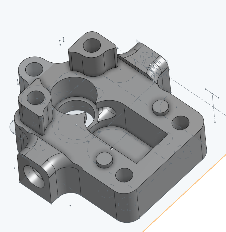
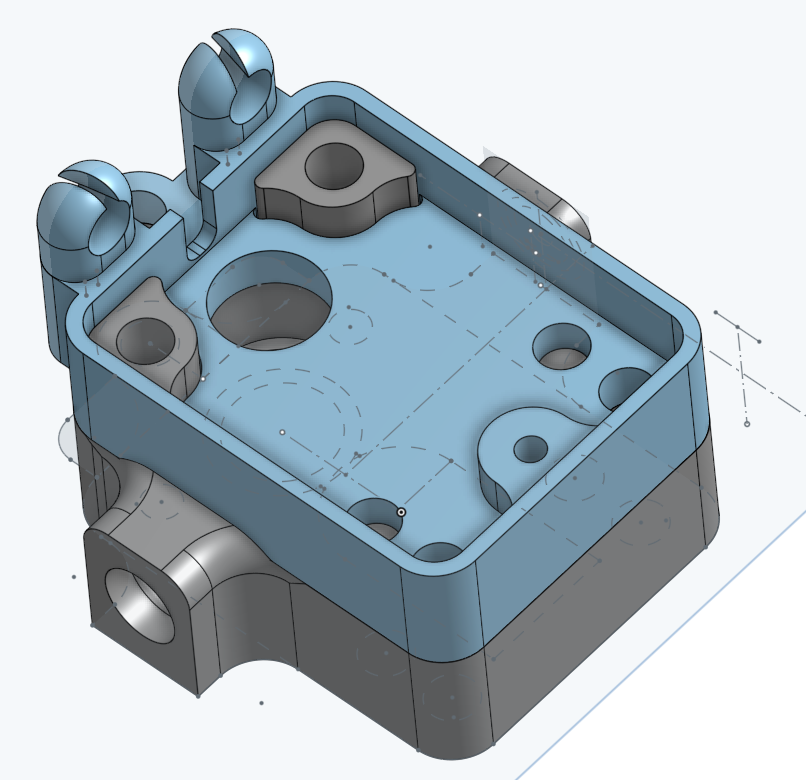
At this point, I should add that I have the MK1 rotating assembly. The MK2 has a shorter hobbed section and fatter magnet. Moving the deck of the body cuts into the reliefs for the PTFE collets, creating a gap where the collets can push the lid up. This didn't seem ideal, so I moved them out to some small extensions. This has the added bonus of giving more length within the housing to hold the PTFE nice and stable.
I made a few "quality of life" adjustments, making the bearing seats and PTFE holes slightly tapered for easy starting without resorting to files or suchlike.
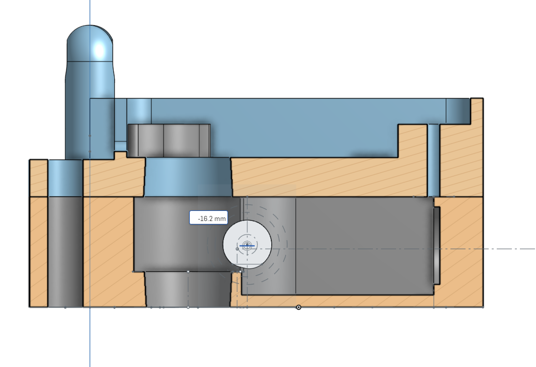
I had a quick think about the idler carrier. I'd designed with slightly more room for a beefier carrier, so came up with something that still allows the halves to be identical, but a little more surface area for the glue joint, and the joint running perpendicular to the layer lines for strength:
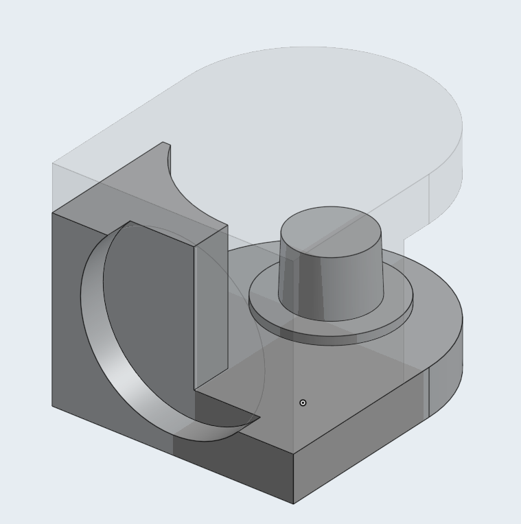
The result:


A quick view of how the standoffs work:


And the strain relief works nicely too:

All printed PLA, 0.1mm layer height, 3 walls, 0.4mm nozzle, 0.4mm line width on a cr**tacular printer
and snapped together with nothing more than a light deburr. M591 D0 from its first print:Duet3D rotating magnet filament monitor v3 on pin e0stop, disabled, sensitivity 26.67mm/rev, allow 70% to 130%, check printing moves every 6.0mm, version 3, mag 131 agc 86, measured sensitivity 26.62mm/rev, min 95% max 104% over 5150.3mm
That's probably accurate. That print was 0.6mm line width, 0.3mm layer height and fairly fast. Just happened to be what came up for printing when the latest prototype was ready. Typically, I'd expect and get 98%-101% on a more standard 0.4mm width .1 or .2mm layer print. I'm happy enough with the mag and agc right there straight out of the box. Yes, it's disabled for the moment. I tend to log M591 for a few prints before sending new designs live in case it starts doing weird stuff and pausing prints that it shouldn't.
I've got some testing to do to make sure this really is as solid as I hope and have been in touch with one of the team about getting hold of a V2 rotating assembly to make sure that version is working nicely too.
I'll start sharing links in a couple of days when I'm sure it's all behaving. I hope I'm not treading one anyone's toes - I figure this is all in the spirit of open source
Thanks for reading!
Excellent job! Would it br possible to have the STEP files (or Fusion360 files) for the V2 Assembly? Id like to make some adjustments to fit it in my printer.....
Thanks!
-
-
@TheDragonLord
Hi, just found your post - sorry for the delay and thanks! I don't use Fusion so STEP is the best I can do:
-
@Lo-Fi said in Redesigned the MFM housing:
@TheDragonLord
Hi, just found your post - sorry for the delay and thanks! I don't use Fusion so STEP is the best I can do:
excellent, thanks
-
What‘s the difference between V1 and V2? Does it depends on the version of the magnetic filament sensor. I have 1.7b… What should I use?
Thank you for your great job,
Pierre -
No more support needed! Another happy user of the magnetic rotary filament sensor with your housing! After 1,5 years of frustration and useless parking… Thank you so much!
Kindly regards, Pierre
-
Apologies for the slow reply! Glad it's working out for you
