Motor noise and print quality
-
@phaedrux said in Motor noise and print quality:
@sethipus The DBot isn't a very good candidate for enclosure. It's way more work than it's worth IMO. I've made do with a plastic shroud that can hang around the entire printer on it's stand. It's like a loose curtain. At the top is an exhaust duct. It works fairly well with ASA, etc, both with chamber temp and fume exhaust, but it's not perfect. 40c at best.
A design like the Voron2 or RailCore II that are designed from the ground up for enclosure would be perfect... if you want another new printer.
I totally hear ya. I do want to move my power supply out of the build area, and I could design a new Duet Wifi controller box that hangs off the side rather than being centered within the left-side frame. I think I could get the bottom enclosed, the sides, front, and rear without too much trouble. The top might be "well enough" enclosed with a little plastic bag-like tent that is tall enough not to disturb the bowden tube. You're 100% right that it's not optimal at all, but I think it could be done. I've got parts (including parts on my printer) that are from ASA, but I've struggled a lot with it warping. My attempts at PC blends almost all ended in warped parts. I even had PC-blend parts that stuck to the bed throughout the print, were annealed in place by placing a cardboard box over the completed print and allowed to heat-soak on the build plate for a couple hours, cool down slowly, and then literally warped after I removed them from the build plate. Other than nylon, I've all but given up the other filaments other than PLA and PETG until I can get my printer enclosed.
I'll have to look at those other designs and decide if I need to have another printer project in my future.
-
@grizewald , I replaced all my toothed idlers with smooth ones, put the flip in the belt on the first run from the stepper on the "outside" runs of my CoreXY system so that the flat side of the belt is always bearing on the idler pulleys, and just finished my first print with it.
The flip made a ginormous difference in the surface quality, and utterly eliminated the "corduroy effect" I was seeing. I'm absolutely kicking myself that I didn't do this when I built the printer in the first place. It's unbelievable. Oh well, you live and learn.
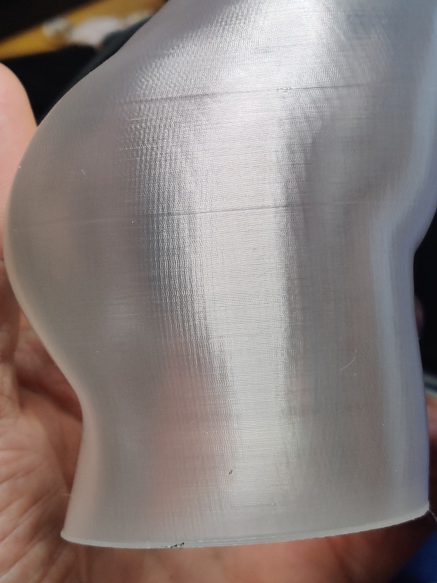
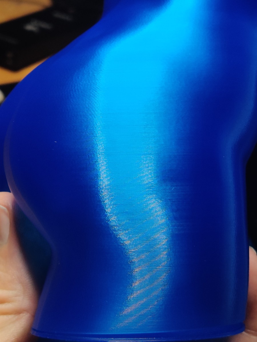
Here are two photos of a relatively innocuous portion of a particular figure. The blue one is the new print with the flipped belts and smooth idlers, the clear one is with the belts not flipped and the teeth rolling over toothed idlers.


As you can see, in the photo of the blue print all of that corduroy effect is completely gone. That corduroy effect has afflicted every print I've ever made on this printer until now. On highly detailed models with no or few flat or relatively flat surfaces, or with filament that doesn't reflect light that much, it wasn't really noticeable. On shiny flat surfaces it was always highly obvious. I almost can't even believe how much of a difference it's made.
-
@Sethipus already shoved the cause, effect and solution. I build pick and place machines, and one of my prototypes had GT2 belt going around a smooth idler with teeth towards inside. My machine has a microscope looking at the work surface and software to measure position relative to a mark, so I could measure this. FYI, the effect is about 0.01 - 0.015mm max. I would predict that it is visible on a shiny surface, as beautifully demonstrated above.
-
@sethipus That's a very conclusive result!
My efforts to add a twist to the belts ran into a few snags. First I noticed that the clamp which holds my hot end had broken (at the rear where it wasn't visible until I took the printer apart in preparation for twisting the belts), so I had to print a new one in PETG this time to make it less likely to happen again.
Then I needed to redesign my part cooling duct so that I could get better access to the eccentric nut which tightens the hot end carriage wheel against the v-slot profile.Both new parts took a few attempts to get just right and that took up most of my weekend.
I finally got everything back together today and I'm re-printing the test piece now.
Noise figures bear out how much noise was being created by the belt teeth running over the idlers. Now I'm getting:
60mm/s 53.1 dbA
90mm/s 53.6 dbA
120mm/s 54.9 dbAPictures to follow once the print completes!
I noticed that the 0.9 degree steppers get fairly toasty compared to the 1.8 degree ones. Half way through the print, I'm seeing 41C on the motors. I'm running them at 1.6A (80% of rated current).
-
@grizewald said in Motor noise and print quality:
I noticed that the 0.9 degree steppers get fairly toasty compared to the 1.8 degree ones. Half way through the print, I'm seeing 41C on the motors. I'm running them at 1.6A (80% of rated current).
if your parts that hold the motors can take this, its not a problem
-
@veti They seem to have stabilised at 41C and the motors are mounted in metal brackets, so no problem at all.
-
@sethipus What are the diameters of the toothed and smooth idler pulleys? I use F608 bearings (22 mm diameter) for idlers in my corexy machine, with no twists in the belts, and never see that type of artifact.
I recently had some of the fine vertical lines appearing in prints in a printer at the Makerspace (SoM), which I recently converted to a Duet WiFi controller. I noticed that the X axis was making quite a bit of noise, as if something was vibrating. After playing with current and ustep ratios, without any improvement, I took it apart to find the problem and discovered that the motor had developed excessive stiction. I thought there might be crud in the top bearing as the shaft was pointing upward, but when I opened the motor and tried spinning the bearings, both turned freely. Close inspection of the rotor found a couple small ferrous metal flakes stuck to them- I suspect they came out of the bearings. There's very little clearance between the rotor and stator, so it doesn't take much to get between them and cause exactly this sort of problem. Once I cleaned everything up (and inspected under a microscope) and reassembled the motor, no more vibration, and no more vertical lines in the prints. This is an industrial surplus motor, so there's no telling how much use it saw before it went into the printer. I put the motor back into the printer and ordered replacement bearings.
-
There is certainly an improvement, but it's not dramatic:
.jpg)
The 120mm/s section still appears to be the smoothest but the most obvious improvement is in the 60mm/s sections which apart from the ringing patterns created by acceleration show no signs of the banding which was there before.
-
@grizewald said in Motor noise and print quality:
@sethipus That's a very conclusive result!
My efforts to add a twist to the belts ran into a few snags. First I noticed that the clamp which holds my hot end had broken (at the rear where it wasn't visible until I took the printer apart in preparation for twisting the belts), so I had to print a new one in PETG this time to make it less likely to happen again.
Then I needed to redesign my part cooling duct so that I could get better access to the eccentric nut which tightens the hot end carriage wheel against the v-slot profile.I ran into a huge snag too. When I replaced my toothed idlers with smooth ones, I also replaced the corner brackets with ones that allowed both pulleys to be replaced without disassembling the printer (for some reason the original D-Bot corner brackets require disassembly to swap out one of the pulleys). The remixed corners I used also stuck down about 20mm or so further along the frame rails. For some reason I overlooked the fact that my Z-axis end stop no longer would fit where it had previously been mounted. Long story short, some severe violence using a bandsaw and a drill allowed me to jerry-rig the z-stop mount enough to fit it in between the bottom of the new corner brace and the wheels of the Z-axis carriage and I'm printing, but the current z-stop mount is a total hack (literally), so I'll have to design a more graceful solution that moves the z-stop to a different location.
As far as heat goes, I've only been running my steppers at 1.1-1.2 amps, and I haven't noticed heat to be much of a problem.
@JuKu yeah I've studied my now-former corduroy effect problem under a loupe and could see that it was a very fine difference in wall thickness that's so slight as to barely effect any dimensions, but on shiny and flat objects (where they lines align) be quite visually noticeable. I'm glad that's now a former problem.
@mrehorstdmd the idlers were 16t-sized. The original D-Bot uses a pair of stacked 623ZZ bearings (flanges outwards) to act as idler pulleys. When I swapped out my toothed idlers this weekend one of the corner braces got stacked 623ZZ bearings, the other one got actual smooth 16t-sized idlers that I happened to have. If I ever design or at least build a new printer I think I'd rather use 608-sized bearings or pulleys rather than these tighter-radius ones, or at least 20t-sized ones, for the larger radius.
-
@grizewald said in Motor noise and print quality:
The 120mm/s section still appears to be the smoothest but the most obvious improvement is in the 60mm/s sections
mechanical (aside from the acceleration ringing) it looks ok to me now.
i think the difference in appearance now comes from the extrusion speed.
the faster you are printing the higher your hotend temperature needs to be.