Maybe this is a clue?
-
@mac said in Maybe this is a clue?:
I also moved the bed from the connections next to the main power in to the connector on the right side of the board.
Make sure you use a bed heater connection capable of the current required for the heater. The bed heater connection on the board is rated higher than the hot end heaters for instance. So if you are powering the bed directly, use the bed heater connections.
-
Are you saying this won’t do?
My expensive crimping tool destroyed all 5 of the metal receivers for the heavy-duty connectors (not connections?).
-
@mac
That won't do.
Post a picture of your crimping tool, please.
Frederick
-
@fcwilt here you go

-
@mac said in Maybe this is a clue?:
@fcwilt here you go
That is only for the connectors you tried sticking onto the pins.
That is not the crimper for the connectors that fit the large or small plastic housings that are used with Duets.
For them you need one of these:

Search Amazon for:
IWISS SN-28B Dupont Crimping Tool for 3.96mm, 2.54mm, 2.5mm Pitch Dupont, JST XH VH Connectors, AWG 18 to 28
Printers: a small Utilmaker style, a small CoreXY and a E3D MS/TC setup. Various hotends. Using Duet 3 hardware running 3.4.6
-
@fcwilt well of course!
Or I could have bought the one with exchangeable jaws in the FIRST place!
-
@fcwilt actually, that’s what I have.
-
@mac said in Maybe this is a clue?:
@fcwilt actually, that’s what I have.
And you had trouble using it to crimp the larger of the two sizes of connectors used with the Duet?
Frederick
Printers: a small Utilmaker style, a small CoreXY and a E3D MS/TC setup. Various hotends. Using Duet 3 hardware running 3.4.6
-
Use the screw down terminals for Out0 to power the bed. The other heater outputs are not rated for that kind of draw.
And you'll need to get the correct crimps/terminals.
Out0 could technically be used with barewire, but a proper spade terminal would be best.
-
@fcwilt only because I used the small jaws.
-
@phaedrux I had it that way initially, but then I was doing a new config.g, and the choices available from the RRF configuration were the pin connectors instead of the screw terminals?
Do you know that there are multiple links to the RRF configuration? In my experience yesterday, when I clicked on those links, based on what I was researching in the documentation, I reached different choices, and only those choices in those versions of the tool?
Or was I having a drug induced dream?
Mark
-
@mac said in Maybe this is a clue?:
@fcwilt only because I used the small jaws.
For the large pins you use the largest section nearest the pivot point.
And it sometimes helps to take a mm or two off the large "ears" the are intended to grip the insulation.
Frederick
-
@mac said in Maybe this is a clue?:
@phaedrux I had it that way initially, but then I was doing a new config.g, and the choices available from the RRF configuration were the pin connectors instead of the screw terminals?
You MUST use the screw terminals for a heated bed. This is out0 on a Mini 5+. Most heated beds draw a large current, and the screw terminals have their own 15A fuse. The hot end terminals are only rated to 6A. If you want to calculate the current draw on your bed, measure the resistance of the bed with a multimeter, then multiply by the supply voltage. eg a 1 ohm bed at 12V pulls 12A.
Do you know that there are multiple links to the RRF configuration? In my experience yesterday, when I clicked on those links, based on what I was researching in the documentation, I reached different choices, and only those choices in those versions of the tool?
When you open the configuration tool, it defaults to using a Duet 2 WiFi, whose pin names are different from Mini 5+. So make sure you choose the correct board on the second page. If you think it's opening a different version of the tool, check the version number on bottom of the first page; currently it is Version 3.3.10. If you do find any links to an old version, please can you post them here?
Or was I having a drug induced dream?
Possibly.
Ian
-
@mac There's a whole section on crimping in the ... guess what ... guide to wiring your Duet 3: https://docs.duet3d.com/en/How_to_guides/Wiring_your_Duet_3#h-3-tools-required
Look under the tabs for the different tools we recommend.Please DO NOT use your wiring like this:
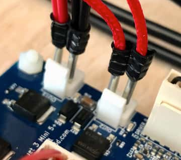
There's just so many things wrong with this:- Poor contact of ferrule with wire/pin
- Exposed metal - risk of short
- Heated bed (high current) on connector designed for medium current
Use the correct connectors, or you are going to have a fire!
Ian
TronXY X5S with Duet 3 MB6HC and Roto toolboard : Cartesian bed-slinger with Duet 3 Mini 5+ WiFi and 1LC : RRP Fisher Delta v1 with Duet 2 Maestro : Polargraph with Duet 2 WiFi
-
Engineer PA21 crimping pliers work well with the JST VH crimps too.
-
@phaedrux Done. I'm coding it in now.
-
@droftarts innovative, out of the box thinking! (But yeah, I get it, and we're going to fix it. Thanks for not putting a photo credit on it.)
