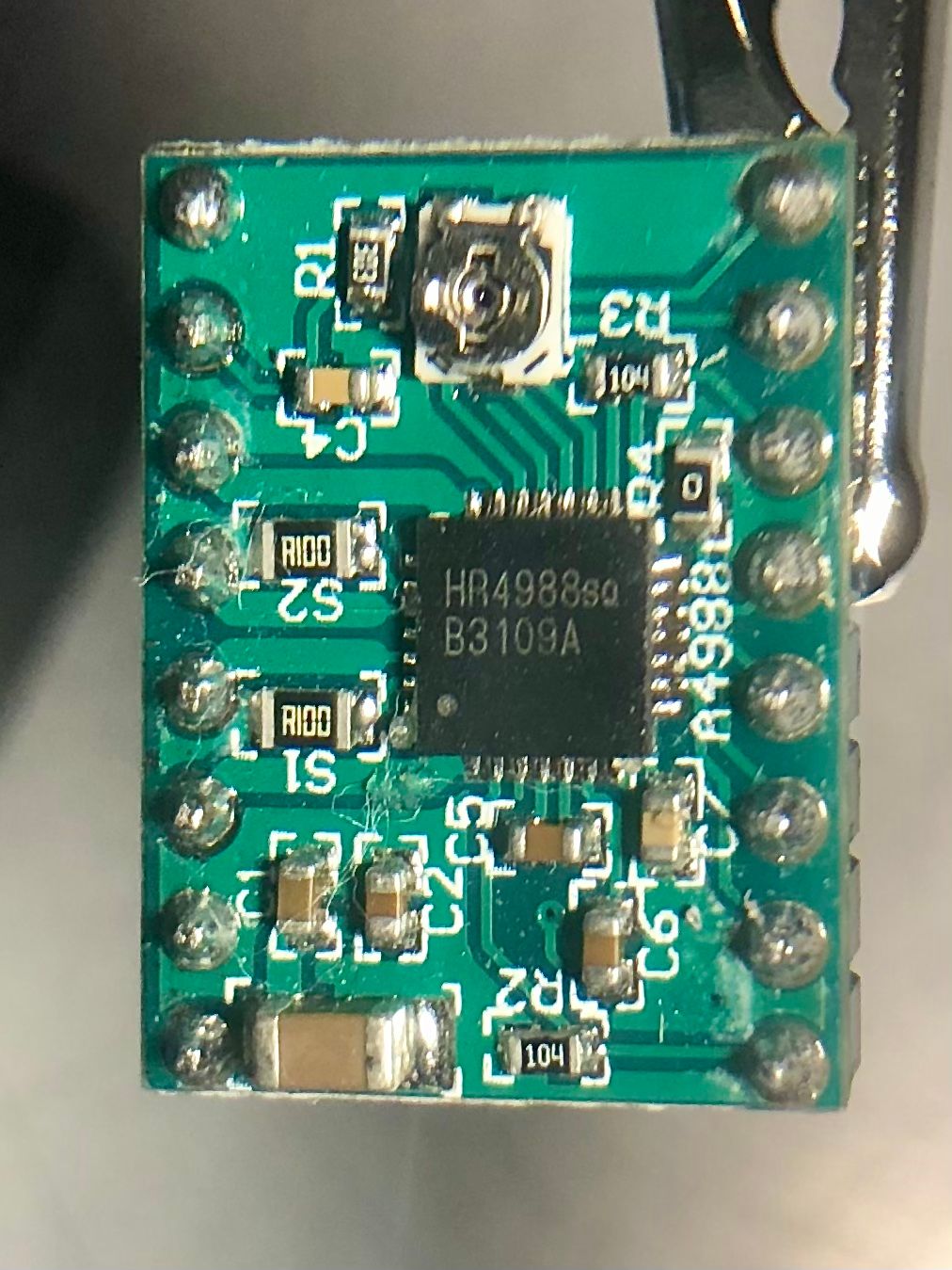
Prepare for Surgery!
-
@droftarts I think I measured .442 volts divided by 8 is .05525 amps?
-
@mac it’s divide by 0.8, so 0.442 / 0.8 = 0.5525A, or 552.5mA. I think you said your motors are rated for 1A? I’m sure 600mA will be fine.
Ian
-
@droftarts well, that’s good to know, I was thinking these motors are gutless, but apparently not.
So now what! I already know that X, Y, and Z phases are properly split connected to the board. The extruder is wired the same, I’m thinking it’s fine too.
What am I doing wrong?
-
I did the measurement. 0.442 /8 is 552.5 ma? So Ian thinks they’re in spec.
-
@mac the maths check out but make sure to check all the drivers in case one got weird settings.
-
This post is deleted! -
@arnold_r_clark worth a try, but it may well be that the ICSP headers aren't configured as a serial port in firmware and only are usable from the bootloader. The fact that people resorted to dumping the firmware via desoldering the chip when they investigated the board indicated so me that may be the case.
-
@oliof he says that after I cut off the spade connectors to put new ternimal connectors on the power and ground from the power supply!
In my defense, I did think about that.
Now to make some new power supply wires just for the board I'm going to SET ON FIRE!
Mark
-
This post is deleted! -
It's an STM32F103 for all that I know. EDIT: See this blog post https://tinkerfiddle.blogspot.com/2019/02/xvico-pioneer-x3-board-reverse.html
-
@oliof thank you, he is the main source of info on that board.
Here’s the results of testing all four stepper drivers.
X motor: .442 / .8 = 552.5 ma
Y motor: .389 / .8 = 486.25 ma
Z motor: .405 / .8 = 506.25 ma
E motor: .420 / .8 = 525 maInteresting that they’re all different.
-
@mac I wouldn't expect them to be all the same, and I would just set them all to 600mA in RRF.
-
@oliof if I could connect that Xvico board to rrf; that would be better than burning it to ashes, I guess.
