AMB Milling Motor & Duet3 MB6HC
-
Planning is a good thing when connecting 'stuff' to the duet control board, so I want to make sure I understand this before I move on...
The helpful guys at Ooznest have provided guidance on how to connect a milling motor to the Duet2 board, but I have a Duet3 so I am (as usual) a little confused!
I haven't got the milling motor yet so can't check their documentation, but does the PWM/digital converter need to be powered at 24V to run this milling motor, or will 12V do it just as well?
I can connect the board to 24V easily enough if I need to from the PSU, but I'm not sure if the converter needs 24V as the PWM output ranges from 0-10V to adjust the speed of the milling motor.
Feel free to explain this to me as if I'm a bit slow on the uptake, because I feel like I am!
Thank you.
Few things are more dangerous than taking the advice of someone who thinks he knows what he's doing.
I'm still on my learning curve, so take everything I say with caution!RatRig 1075, Duet3 MB6HC, Sorotec SFM 1000 PV-ER milling motor, Hobbyist
-
@nightowl999
Can you post a link to the motor you are planning on using?
SeemeCNC Rostock Max V3 converted to V3.2 with a Duet2 Ethernet Firmware 3.2 and SE300
-
@nightowl999
There should not be too much difference between the Duet 2 and 3.
How did they say to connect it to the 2?
Frederick
Printers: a small Utilmaker style, a small CoreXY and a E3D MS/TC setup. Various hotends. Using Duet 3 hardware running 3.4.6
-
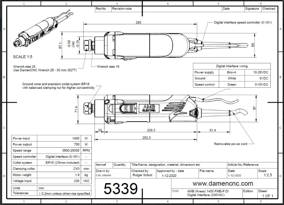
This one, @alankilian.
Few things are more dangerous than taking the advice of someone who thinks he knows what he's doing.
I'm still on my learning curve, so take everything I say with caution!RatRig 1075, Duet3 MB6HC, Sorotec SFM 1000 PV-ER milling motor, Hobbyist
-
@fcwilt Ooznest provide this guide, but they don't use the Duet3 (although they supply it!).
-
@nightowl999
See if this makes sense to you:

Frederick
-
@fcwilt It does, but I can't use the Out9 at 24V because I've got 12V fans from Out8. I suppose I could connect the fans in series, if I needed to use 24V for the milling motor, though.
It's been suggested I could use the Out9 3+2pin together as it's for a PWM/Laser/Servo connection. It's 12V, but the supply to the converter only needs to be between12-30V, but I'm just waiting confirmation on how I need to connect the header and the converter together!
Also, I use the two corresponding connections you've shown as the GND and VIN from the PSU, but I've got a spare pair of of OUTs!
Few things are more dangerous than taking the advice of someone who thinks he knows what he's doing.
I'm still on my learning curve, so take everything I say with caution!RatRig 1075, Duet3 MB6HC, Sorotec SFM 1000 PV-ER milling motor, Hobbyist
-
@nightowl999
It looks like you're all set.
-
Not yet, @alankilian, but it's close!

-
@nightowl999
What's the issue?
This shows you can power the control-interface of the spindle from 10-26 Volts DC and control it using the PWM-to-Analog converter listed in your previous link.
-
@alankilian The issue is I don't know what I don't know
 - but I've not seen this diagram before, so it's a step forward.
I'm not sure I fully understand how this should work, but I think the three cables of the milling motor (Brown, White and Green) would be connected to Port 4 (shared), 5 and 6 respectively, but that's what I'm not sure about. I know the 12V and GND from Out9 connect to Pin 3 and 4 respectively, and I think out9 and 5V_EXT connect to Pin 1 and 2 with the GND on that header unused.
I also think I would need to change the jumper on the converter to 5V.
There are more cables than connectors!
-
@nightowl999
THIS page you linked to says how to wire the PWM converter to the Duet.
PWM converter has 4 inputs (2 power + 2 pwm input signals) and 2 outputs (0-10V voltage). Make sure the yellow jumper is on the 24V pins as we are using the duet pwm signal output which is 12/24V.
Power wiring to the PWM converter
- Connect the “VIN” power pin on the duet board (see image) to port 3 on the pwm converter “power supply + (12-30V)”
- Connect the “GND” power pin on the duet board to port 4 on the pwm converter “power supply – (GND)”
Pwm signal wiring to the pwm converter using HEATER E0 of the duet board
- Connect “VIN” from heater E0 to port 2 “PWM input + (din+)” on the pwm converter
- Connect “E0-” from heater E0 to port 1 “PWM input – (DIN-)” on the pwm converter
THIS page you liked to says how to wire the spindle.
- Brown to “VIN” connector of the duet power supply pin
- Green to port 6 “voltage output + (AO)” of the pwm converter
- White to port 5 “ voltage output – (GND)” of the pwm converter
- Connect port 5 “ voltage output – (GND)” of the pwm converter to the “GND” pin of the power supply on the duet board
- THE LAST STEP (port 5 to GND pin duet) IS REALLY IMPORTANT! You create a common ground between the spindle and pwm converter/power supply
Now if you have 12 Volt fans, can they be run continuously, or do you NEED variable-speed fans?
-
@alankilian It's the relationship between the separate bits I was struggling with, and why I was trying to clarify the changes I would need to make from the Duet2 connectors and those on the Duet3, sorry.
The PWM signal from the Duet3 is not 12/24V as far as I can see, but 5V from OUT9 PWM header. It's that 2+3 pin set I was hoping to use.
I've powered the converter from the 12V and GND pins on the Duet3 and I'm (more) confident in how to connect the milling motor to the converter itself. It's just the 3-pins from the Duet to the converter I'm struggling with.
Sorry, but I'll get it - and then it will be there forever!
-
@nightowl999 said in AMB Milling Motor & Duet3 MB6HC:
@fcwilt It does, but I can't use the Out9 at 24V because I've got 12V fans from Out8. I suppose I could connect the fans in series, if I needed to use 24V for the milling motor, though.
The only reason I said to use V_FUSED was that it is more or less the same as they said to use for the Duet 2. You can use the 12v setting for the Duet 3 jumper and the 24v setting on the PWM convertor.
If I am reading it correctly a 12v PWM signal should drive the PWM convertor.
It's been suggested I could use the Out9 3+2pin together as it's for a PWM/Laser/Servo connection. It's 12V, but the supply to the converter only needs to be between12-30V, but I'm just waiting confirmation on how I need to connect the header and the converter together!
I have no idea what Out 9 3+2 means.
Also, I use the two corresponding connections you've shown as the GND and VIN from the PSU, but I've got a spare pair of of OUTs!
Yes you can connect to the POWER OUT connector if you choose. I was simply trying to mirror the Duet 2 setup as best I could.
Frederick
-
Thank you, @fcwilt.
@fcwilt said in AMB Milling Motor & Duet3 MB6HC:
You can use the 12v setting for the Duet 3 jumper and the 24v setting on the PWM convertor.
Yes you can connect to the POWER OUT connector if you choose...
OK, thanks for clarifying these points for me.
The Out9 3+2pin is this bit on the Duet3:
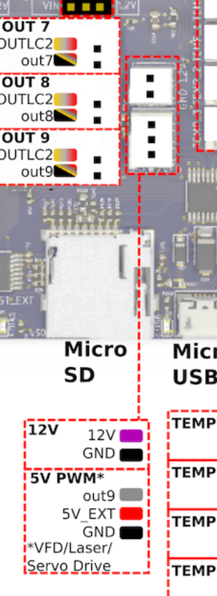
I'm actually drawing this on a piece of paper!
-
@nightowl999
I think those connectors are just to make it easy to pick up 12v for whatever purpose and/or the normal Out 9 connection plus 5v.
The normal Out 9 connection is either going to be a 12 volt PWM signal or a V_FUSED volt PWM signal depending on the setting of the jumper previously mentioned.
Frederick
-
OK, @fcwilt. Thanks again
-
@nightowl999 said in AMB Milling Motor & Duet3 MB6HC:
OK, @fcwilt. Thanks again
Let us know how it all goes.
Frederick
-
@fcwilt Fear not, I will!
One last thing before I sink myself into a comfy chair... all the GND connectors on the Duet boards are common and connected to each other, are they not?
This might make connecting things a little easier.
-
@nightowl999 said in AMB Milling Motor & Duet3 MB6HC:
@fcwilt Fear not, I will!
One last thing before I sink myself into a comfy chair... all the GND connectors on the Duet boards are common and connected to each other, are they not?
This might make connecting things a little easier.
Yes GND is GND but they may not all have the same current carrying capacity. A GND for a power connection will likely use a wide copper trace (or two) on the PC board to carry more current. A GND for a signal connection will likely use a narrow copper trace due to lower current carrying requirements.
So choose your GND connections carefully.
Frederick